


How to Install 600 Amp T-Body Elbow Terminations
600 Amp T-Body elbows connect padmounts to the grid. Learn how to prepare and install T-Body connections on your transformer.
How To's
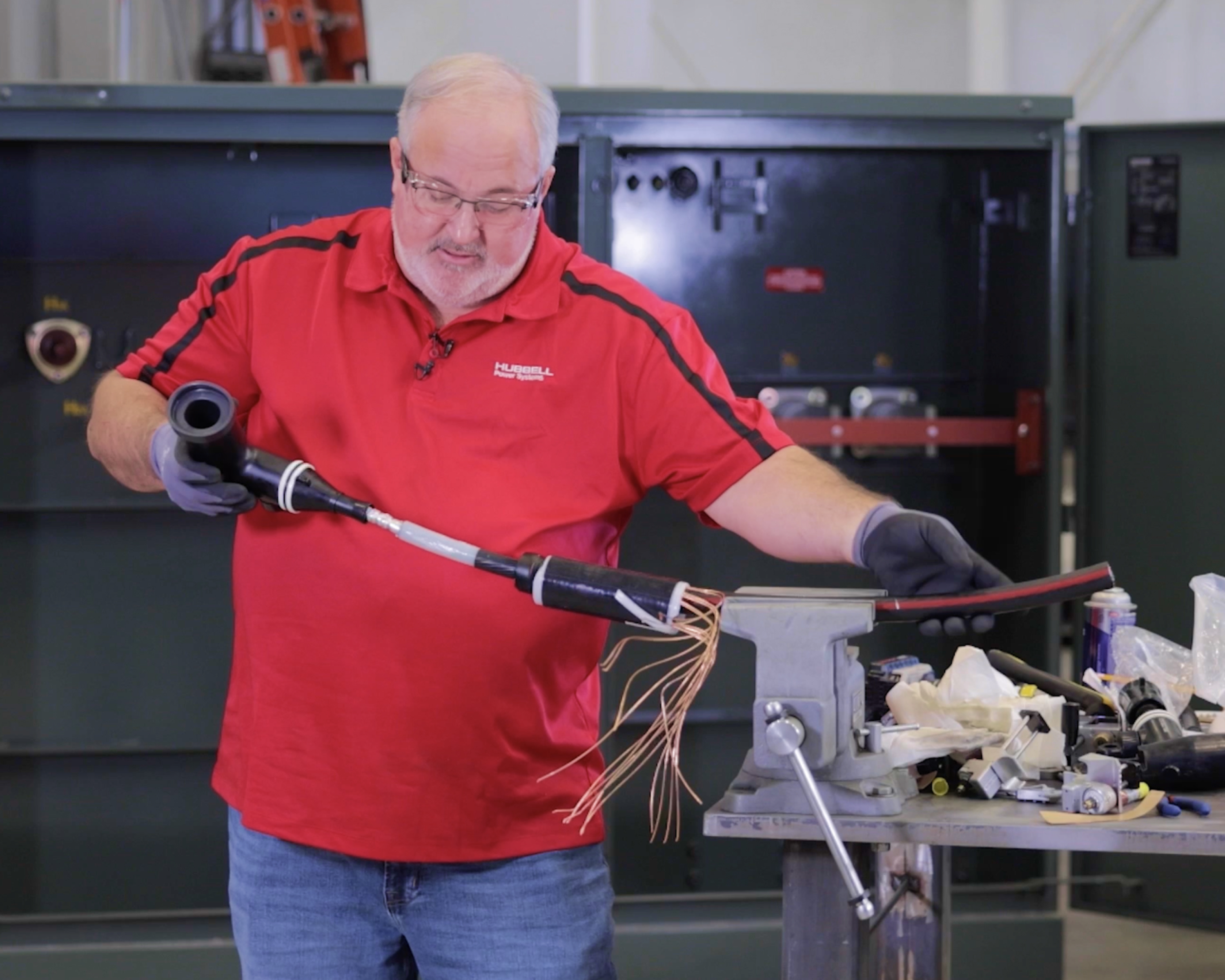
T-Body elbow terminations connect electrical distribution cables to deadbreak transformer bushings. In this article, we will provide a step-by-step process for installing a 600 amp T-Body elbow termination.
Note: This article is not a replacement for the manufacturer's instructions. Please reference the instruction manual that came with your loadbreak elbows for installation guidance.
Tools you will need:
- Marker
- Cable scoring tool
- Ruler
- Elbow kits
- Pliers
- Mastic tape
- Electrical tape
- Cable cutter
- Wire brush
- Lug crimp
- Torque wrench
- Power drill
- Cable cleaner
- Jacket removing tool
Continue reading or check out our video guide below on installing 600 amp T-Body elbows.
Installation Process
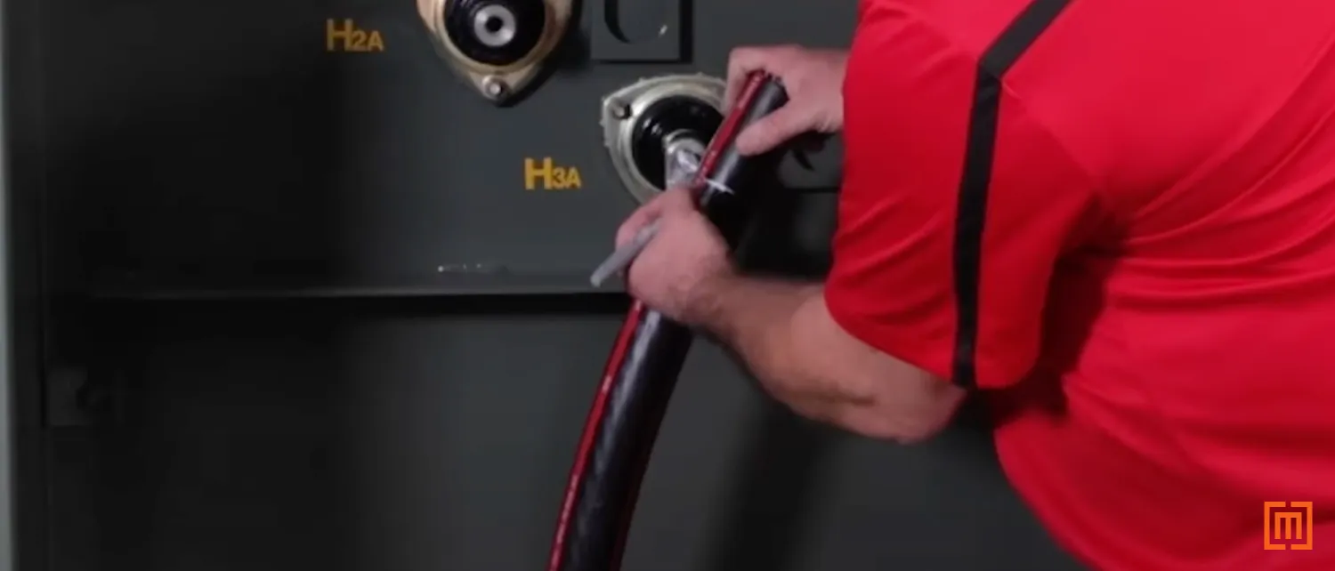
1. Inspect your Padmount’s Bushings
Open the primary side of your padmount transformer and identify if it is set up for a loop or radial feed system. If you are using a loop feed transformer on the end of a radial line, you will need some kind of arrester protection on three bushings not in use. This will protect the unit from lightning and switching surges. Keep in mind, you will need bushing adapters to connect 200 amp loadbreak arresters.
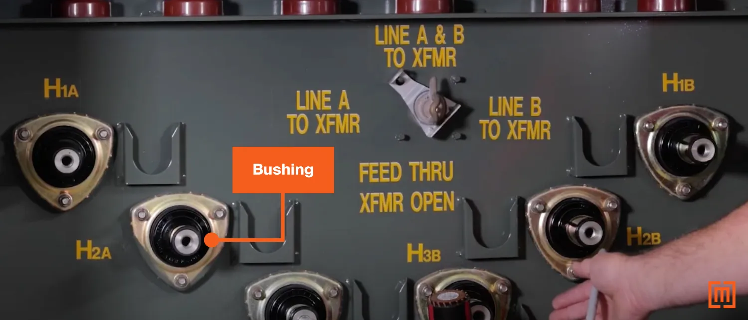
When making up connections with a T-Body, take care to line the connector up with the bushing so that it lays flat. This will allow the connector to transfer energy safely to the transformer.
2. Measure the Cable
Hang the lug on the bushing. Line the cable up and center the cable over the bushing. Make a mark on the cable at the center of the bushing.
3. Section the Cable
When preparing a T-Body, always make sure your cable is as straight as possible. This will help make future cable cuts clean. This will also save you time later on. After straightening the cable, measure and mark 14 ¾ inches from your first mark (the one you made at the center of the bushing).

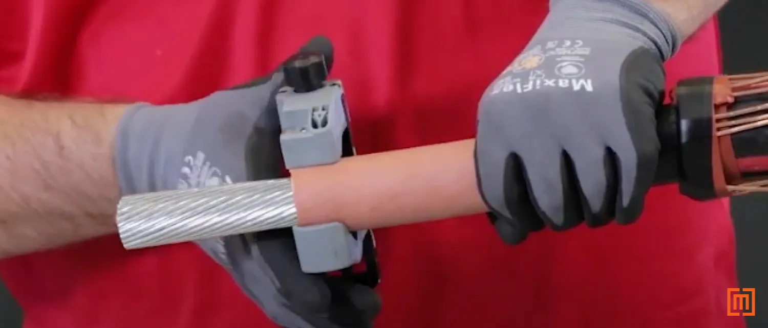
4. Remove Cable Jacket
Use your cable scoring tool to make a square cut at the 14 ¾ inches mark. Then spiral the scoring tool until you reach the end of the cable.
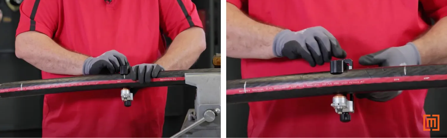
Take pliers and remove the jacket from your cable.
5. Fold Concentric Wires
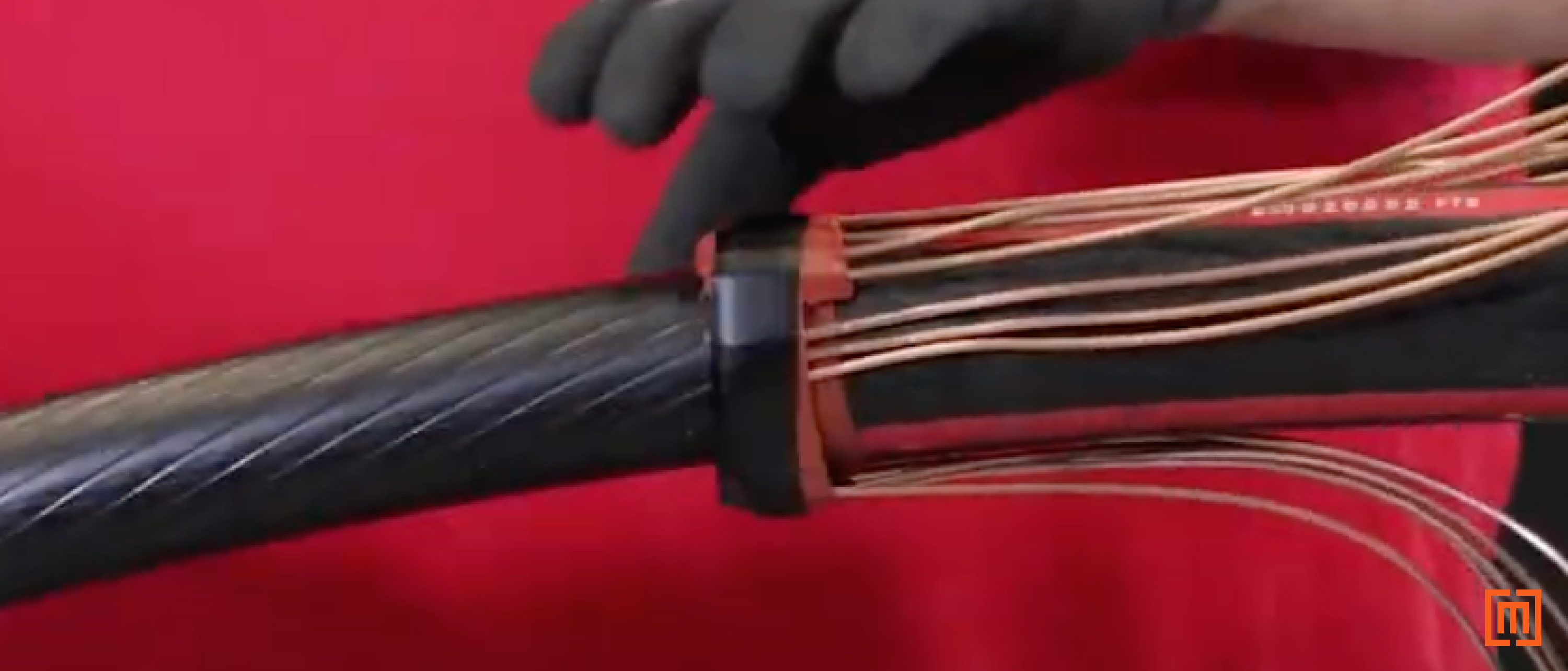
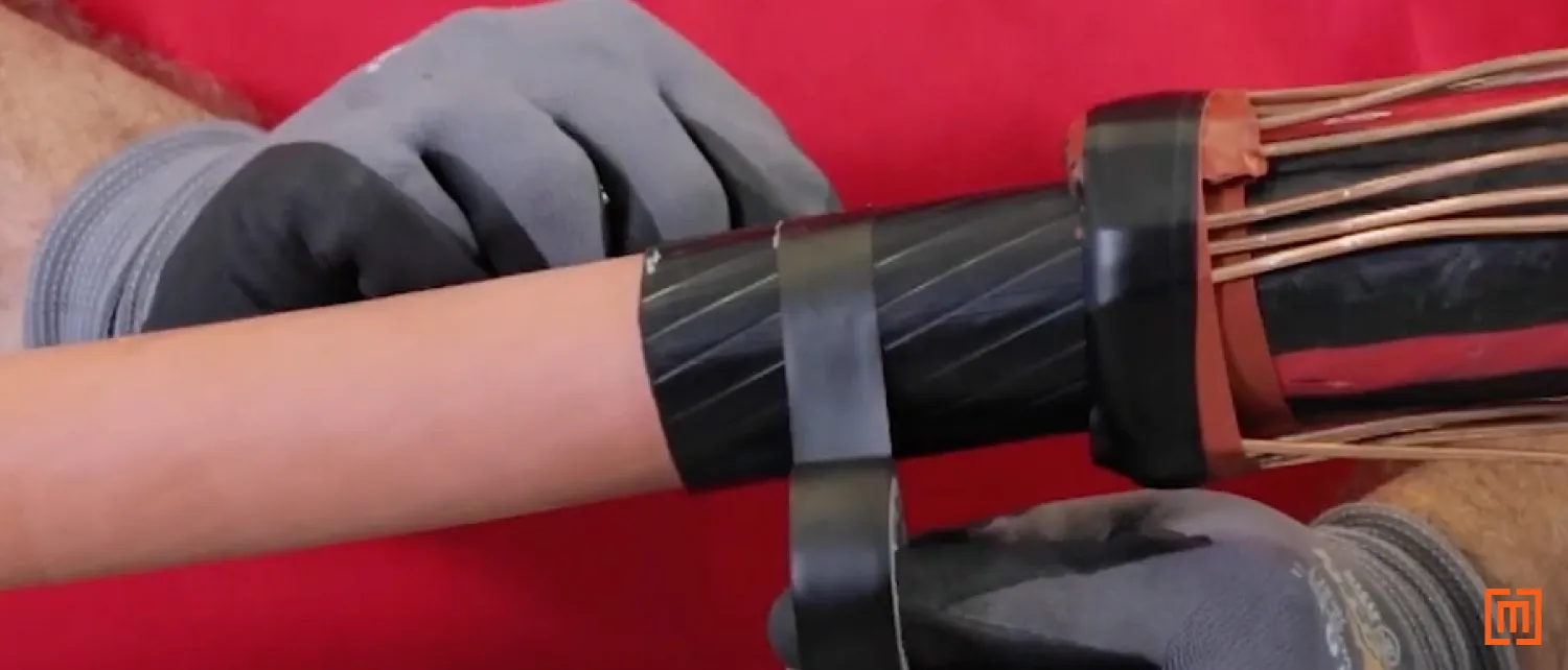
Once the jacket is removed, put a ring of mastic tape around the edge of the cut jacket. Pull the concentric cables back towards the mastic tape.
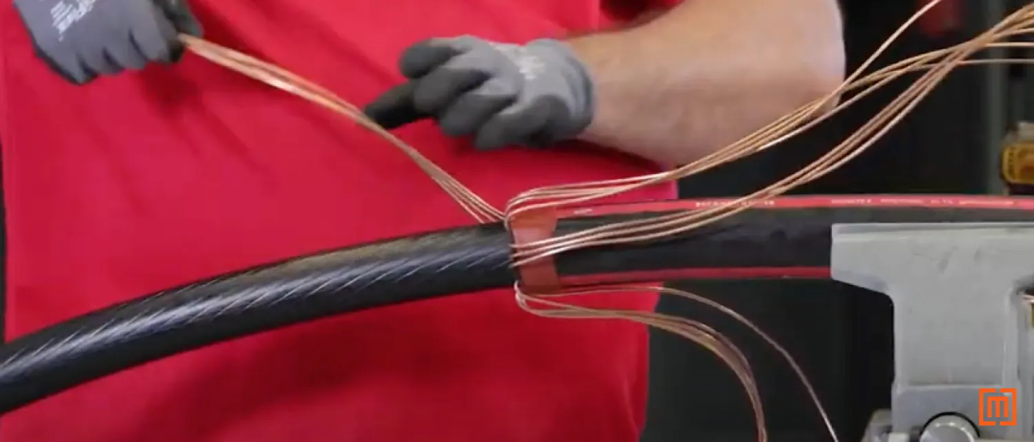
Tap the concentric cables into the mastic. Then secure the wires with another layer of mastic tape.
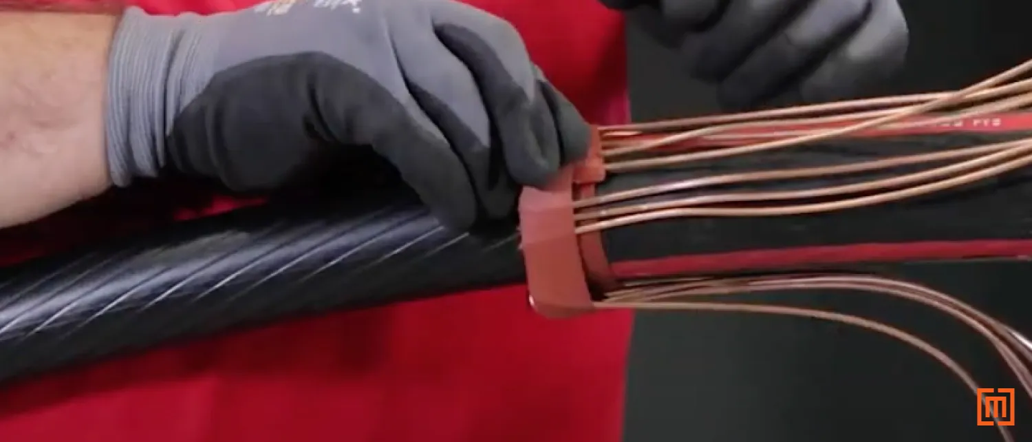
Cover both pieces of mastic tape with a strip of electrical tape.
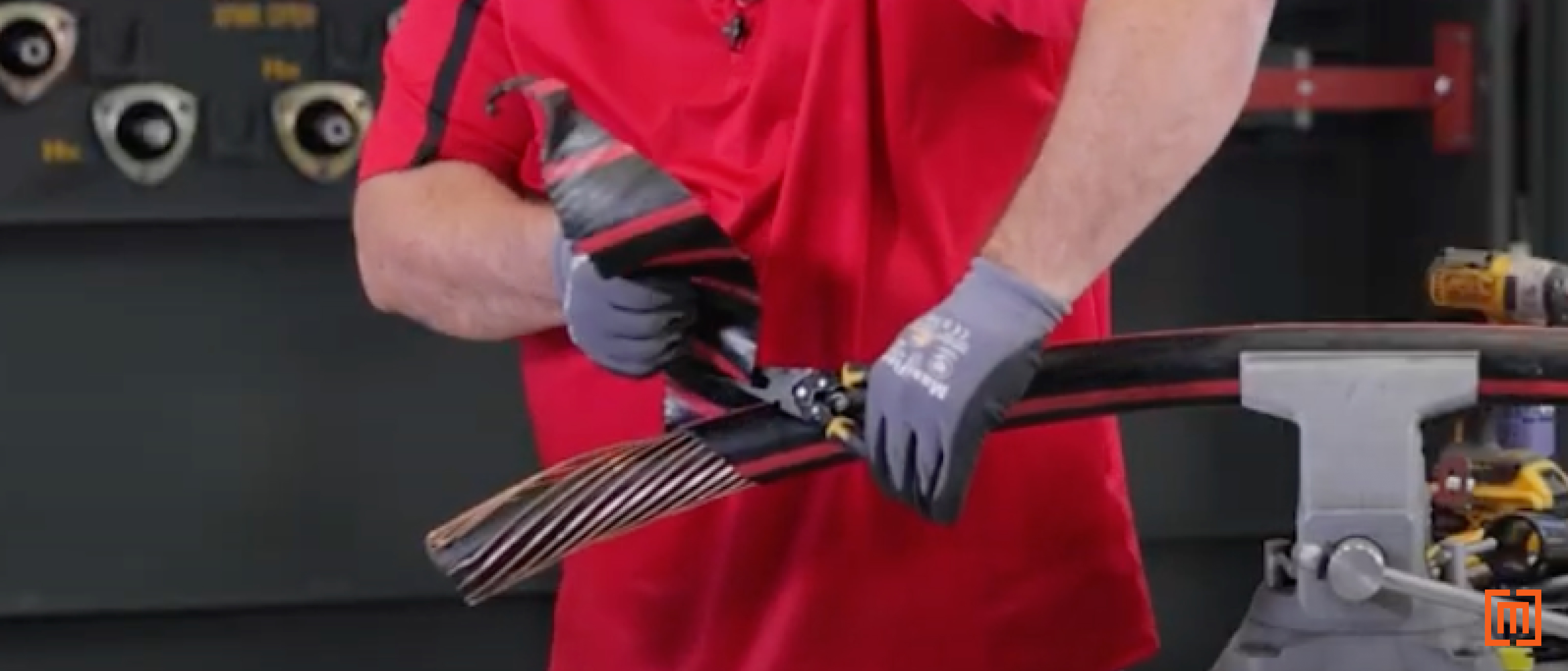
6. Cut off Excess Cable
Once electrical tape is on the cable, measure 13 inches up from the tape and make a mark with your light marker.
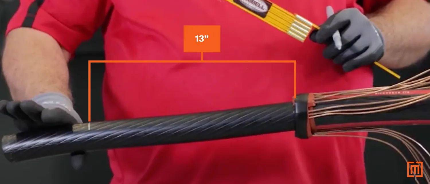
Cut the cable at that mark. What you should be left with is 13 inches of cable measured from the electrical tape.
7. Expose Conductor
Now, you need to expose the conductor so you can slide the cable lug onto it.
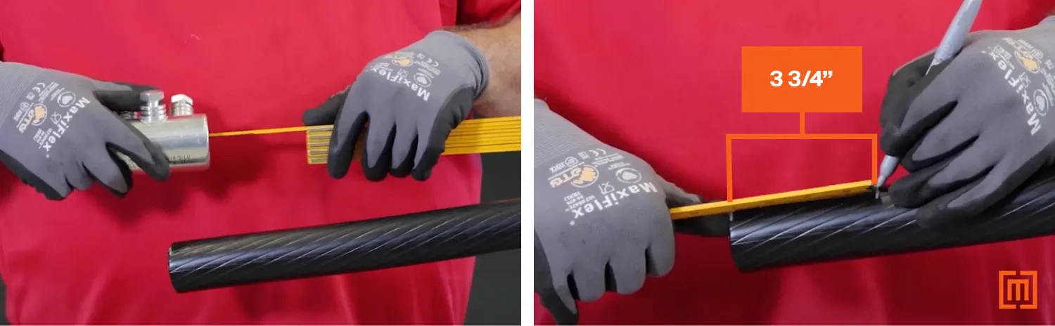
Measure the Lug
You can use shear bolt type lugs or compression lugs for your T-Body. For shear bolt types, measure the inside of the lug to determine how far you should cut the insulation back. In the pictures below, we measured 3 ¾ inches of lug depth and marked it on the cable.
Strip the Insulation
Then, take an insulation stripping tool to cut the insulation down to that mark. Spiraling the tool in towards the mark will help you cut through the insulation. When you get close to the mark, adjust the angle of the tool so you only cut off a little bit of insulation with each turn. DO NOT cut off any insulation past the mark.
8. Remove Cable’s Semiconductor Layer
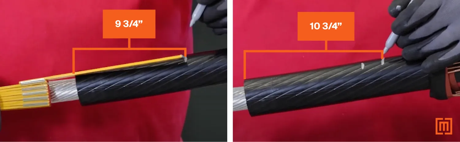
Next, from the end of the conductor, measure 9 ¾ inches and make a mark. Then measure one more inch and make another mark (at 10 ¾ inches). The first mark is the point where you need to remove your semiconductor layer. The second mark is where your cable adapter will stop. After measuring, your cable should look something like the second picture below.
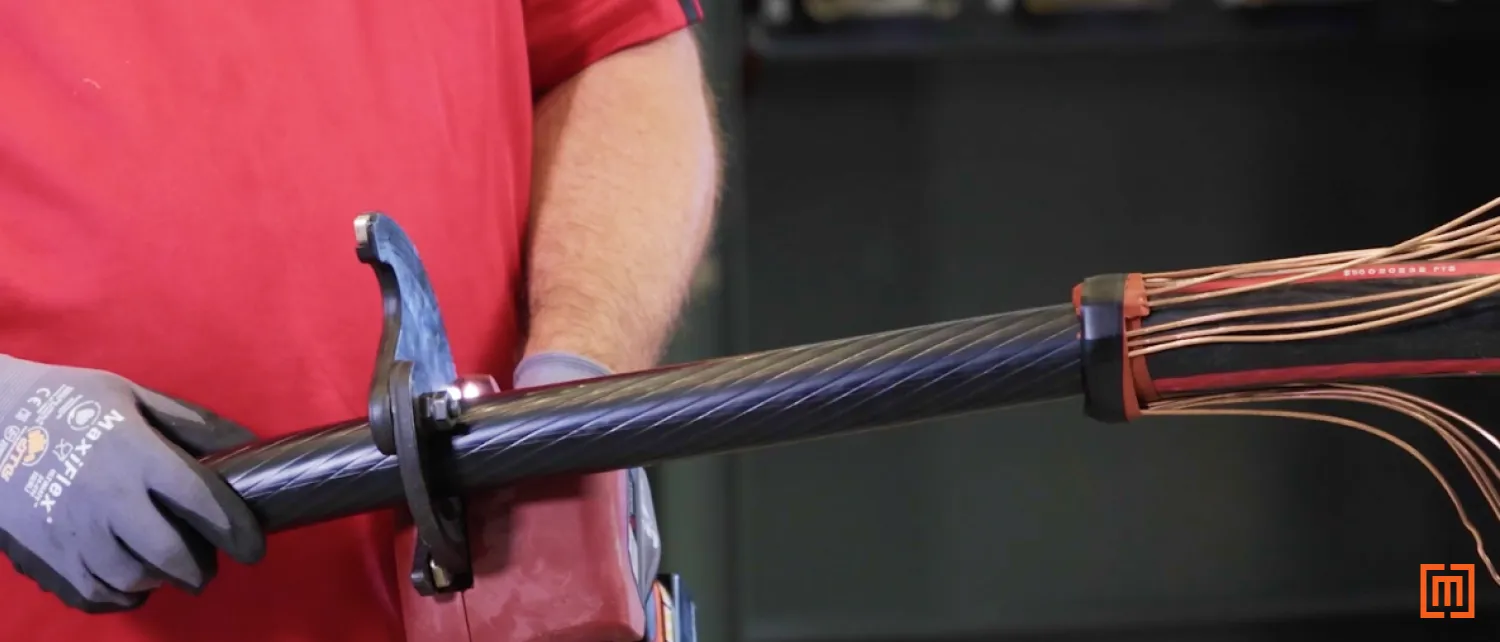
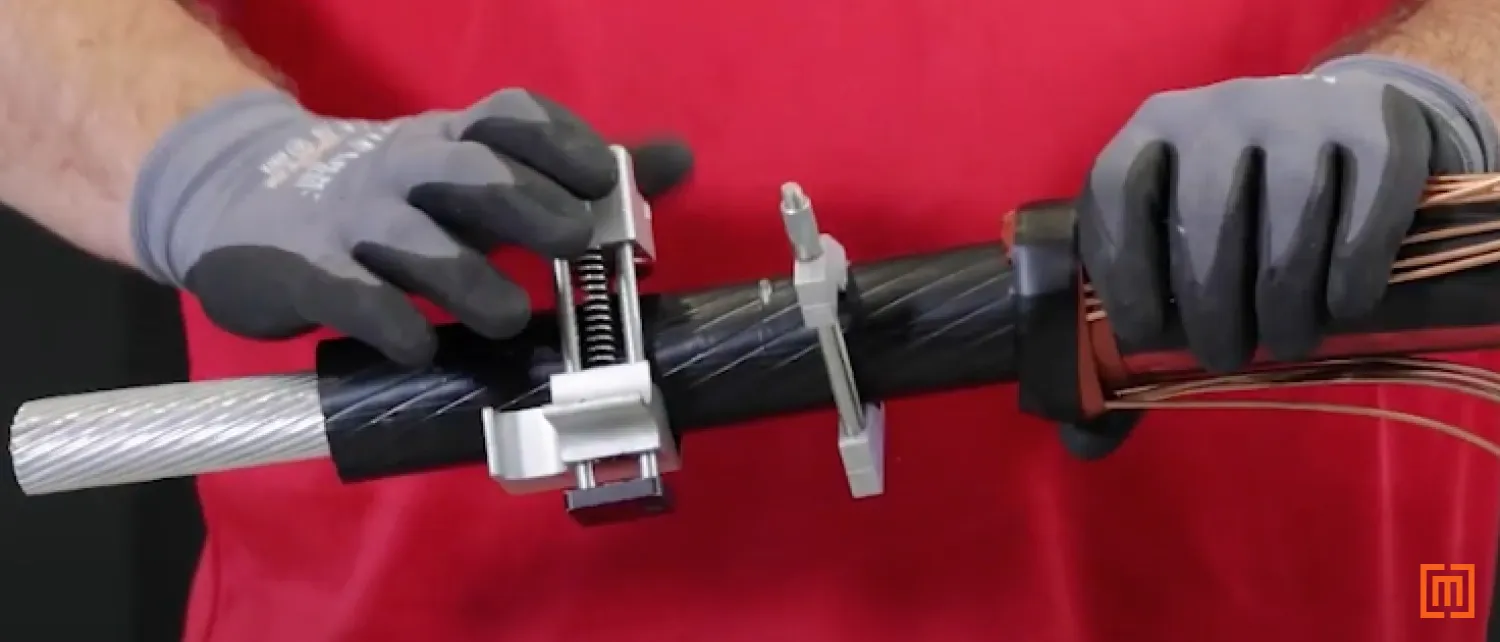
9. Reveal and Bevel Insulation
Use a scoring tool to make a perfectly square cut around the first mark at 9 ¾ inches. Then adjust the scoring tool and spiral out to the end of the cable.
Do not cut so deep that you end up damaging the insulation.
After the insulation is revealed, take the chamfering tool and bevel the end of the insulation. This will help your cable adapter slide on easier.
10. Prepare Insulation for Cable Adapter
Take some electrical tape and wrap it around the 10 ¾ inch mark on the cable. This is the second white line that is closer to your concentric neutral cables. The electrical tape will help you stop the cable adapter at the perfect spot.
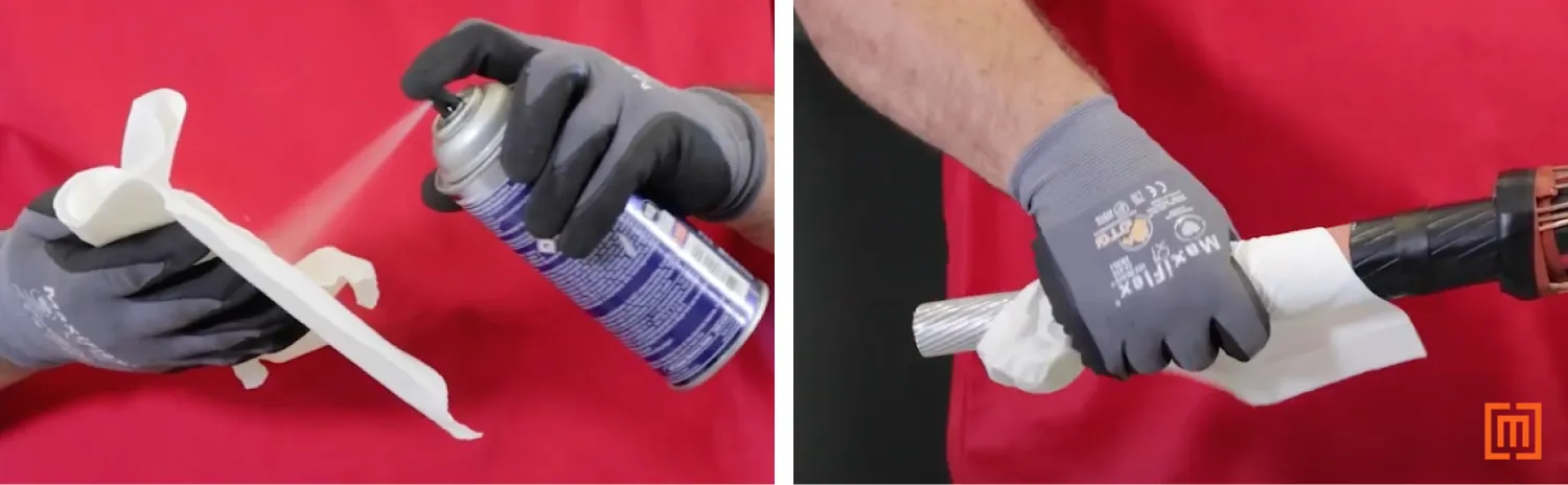
Then, make sure you use the proper cable cleaner to clean the insulation. Spray the cable cleaner into clean paper towels and thoroughly wipe down the insulation.
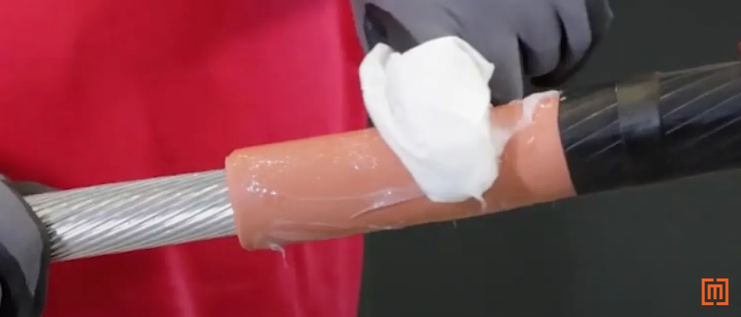
Then apply silicone to the insulation and rub it in with a clean paper towel. As you wipe the insulation, the silicone will fill any imperfections. Make sure that there are no dry spots when applying the silicone. Failure to apply enough silicone could result in air voids or other issues.
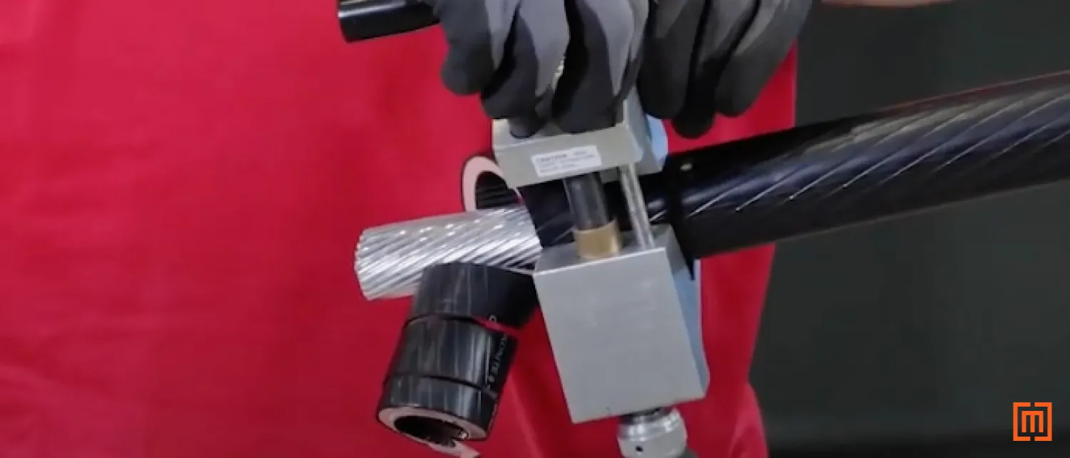
11. Slide on Cable Adapter
Slide on the cable adapter until you reach the electrical tape at your previous mark. Wipe off any silicone that was pushed to the end of the adapter.

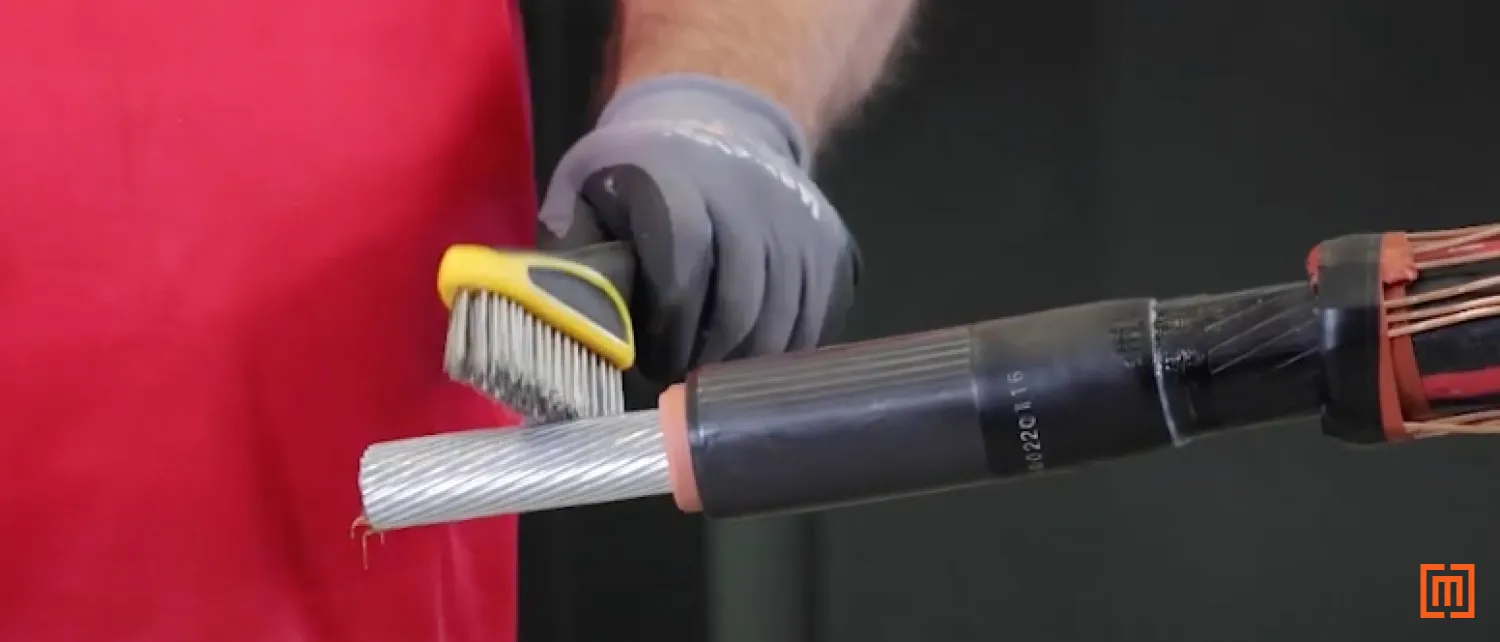
12. Install Connector
Make sure that you orient the shear bolt connector so that the flat side connects seamlessly with the padmount bushing. Then, wire brush the exposed conductor section of the cable.
Note: Some connectors come with a centering ring. If required, add the centering ring before your connector.
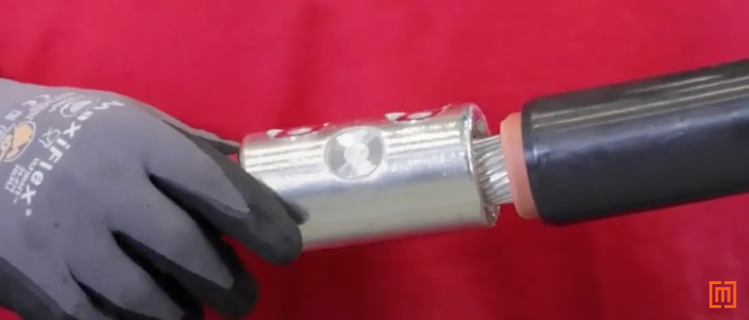
Slide the connector onto the metal cable.
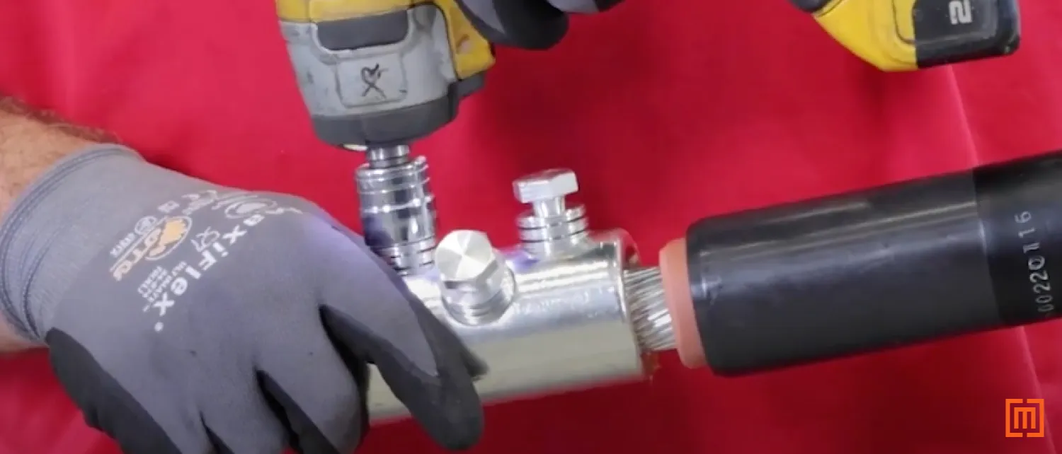
Once the connector is firmly situated on the cable, use a power drill to tighten all the bolts. Start at the bottom and work your way to the top. Once the bolts are tight to the connector, spin the shears off.
If you're using a compression lug, ensure that you use the right crimp tool, crimp pressure, and the right amount of crimps for your application.
13. Clean Cable Adapter
Next, slide the T-Body jacket seal over the lug and cable. Spray some cable cleaner into paper towels and wipe down your cable adapter. Then apply and spread a layer of silicone around your cable adapter.
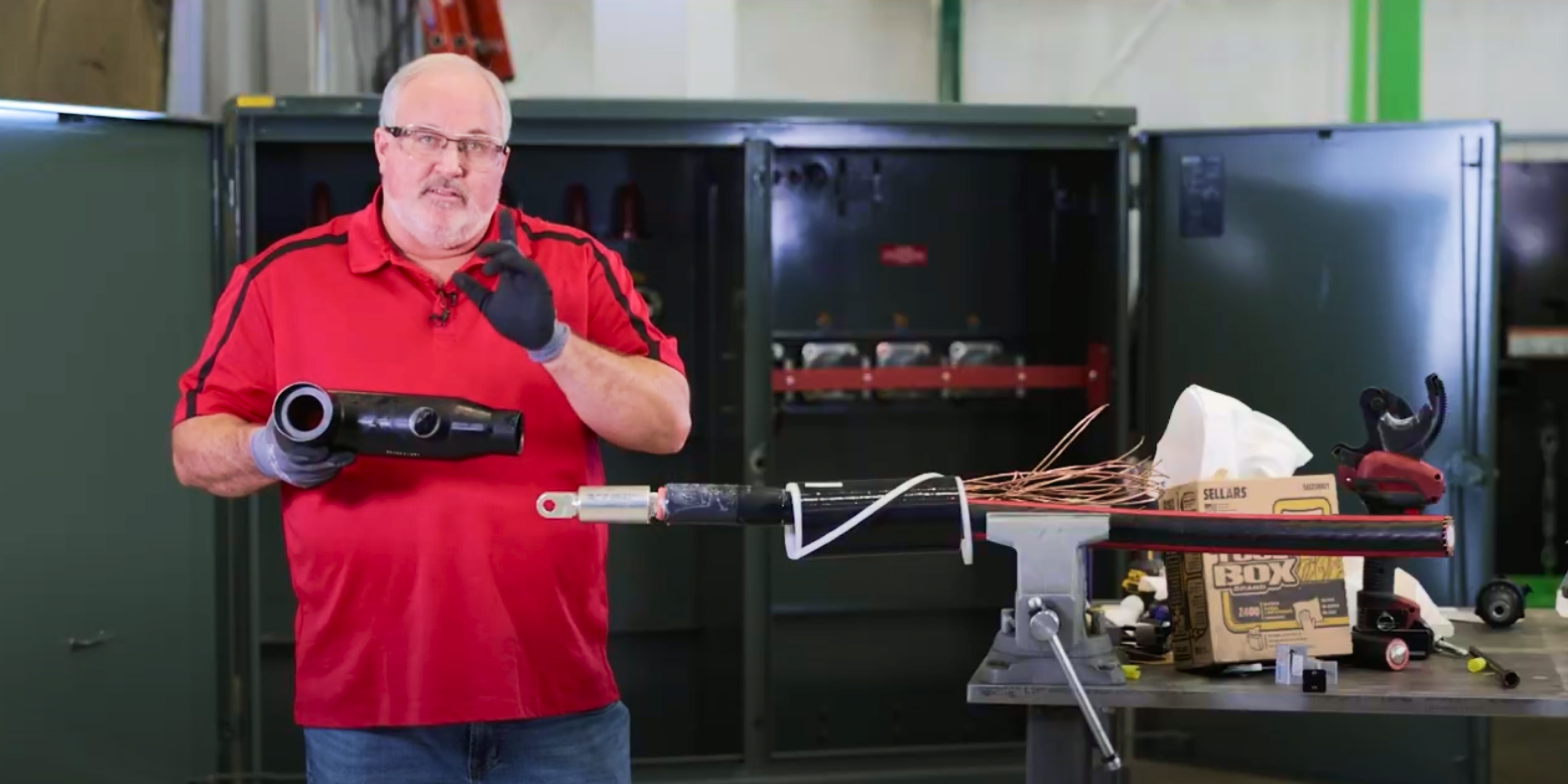
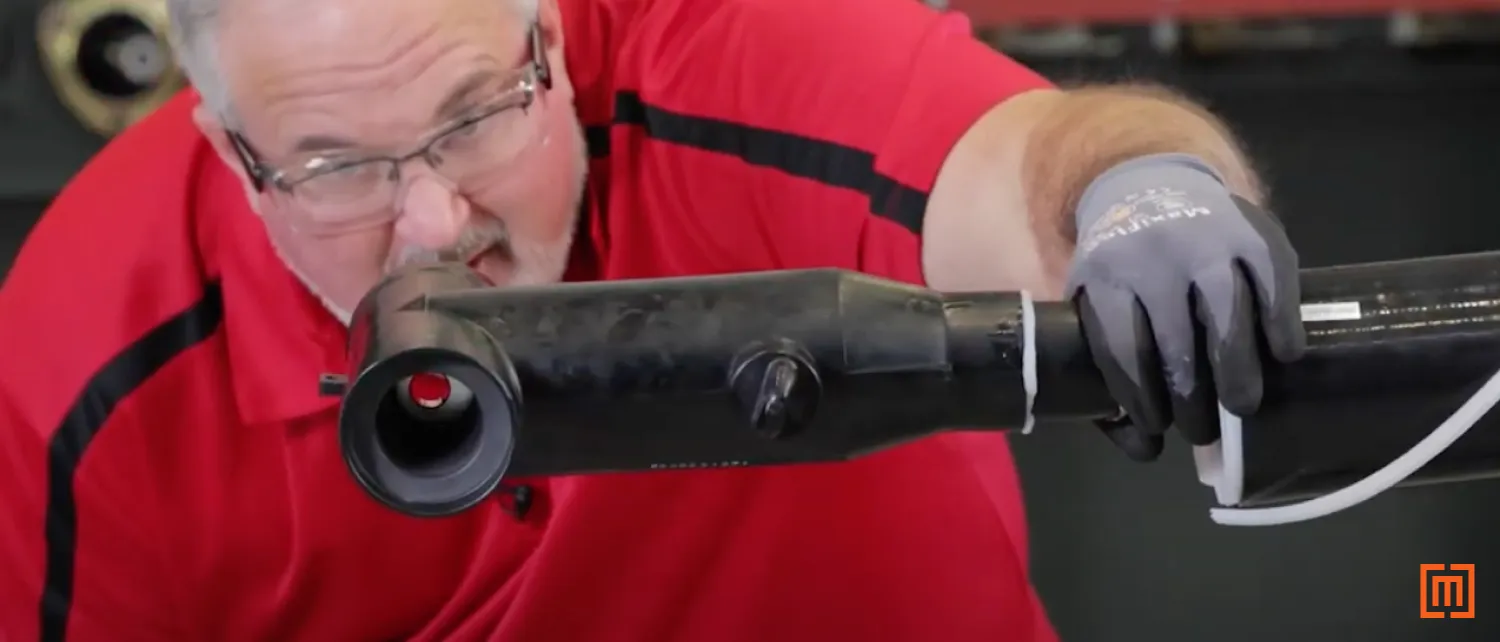
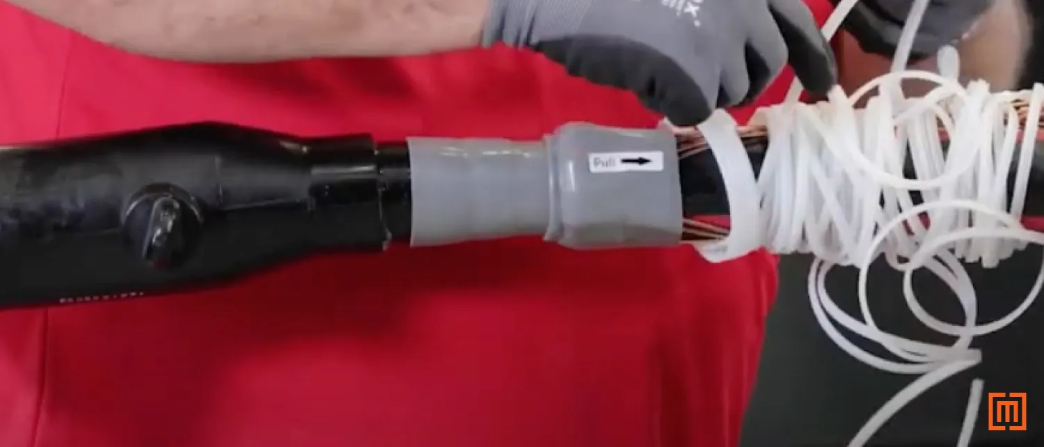
14. Install T-Body
Spread a layer of silicone inside the bottom opening of your T-Body. Make sure that your T-Body is oriented to slide in line with the lug. Make sure that the test point on your T-Body is facing out. Hold your cable adapter and keep it from moving while you slide your T-Body on. You should be able to look through one side of the T-Body and see through to the other side.
At this point, unwrap the jacket seal so that it covers the wires and the remaining sections of the cable adapter.
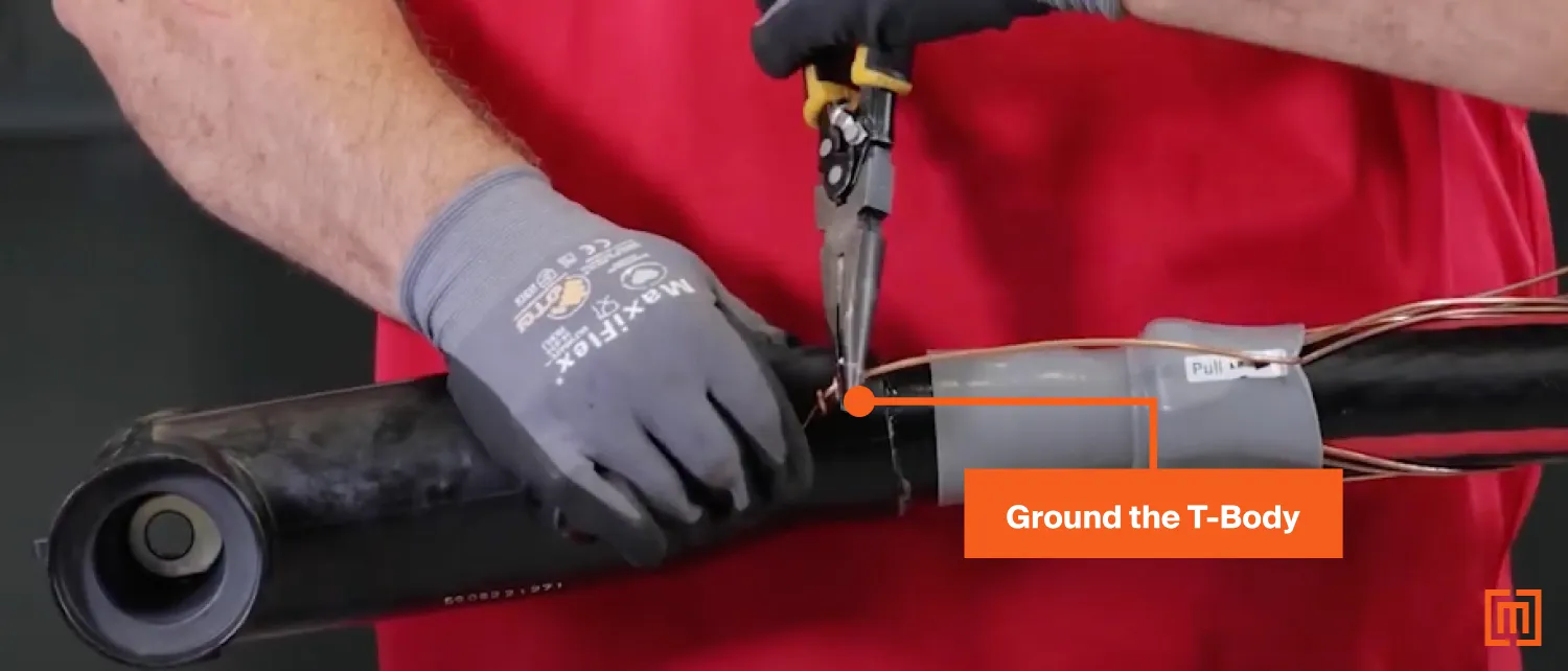
15. Ground T-Body
Take one of the concentric wires and wrap it through the grounding loop on the T-Body. Use some pliers to tightly wrap the excess wire around itself multiple times.
16. Installing 25 kv vs 35 kv T-Body
The process for attaching a 35 kv T-Body to a cable is very similar to installing a 25 kv T-Body. The only difference is that a 35 kv T-Body has longer cut back dimensions to accommodate a larger T-Body and cable adapter. Check the T-Body installation manual for details.
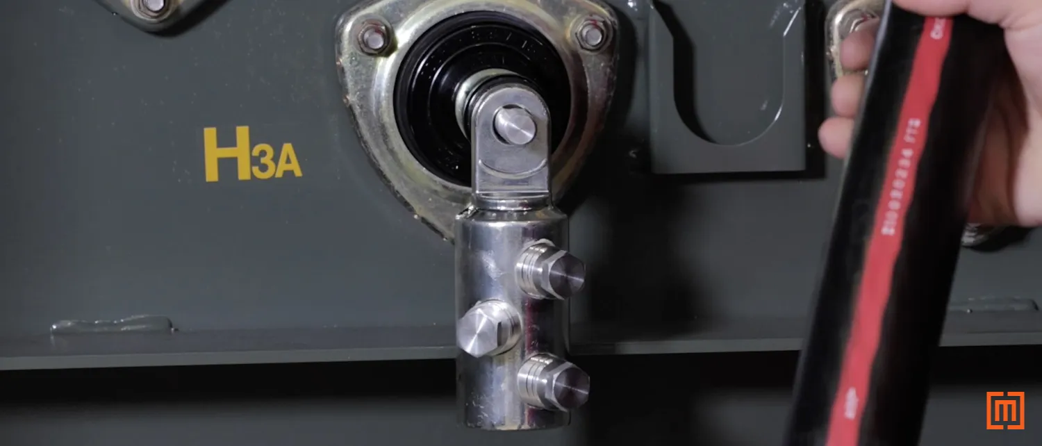
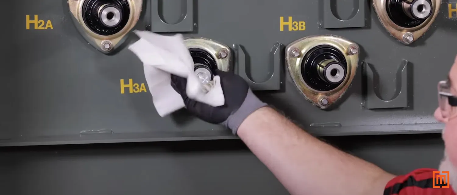
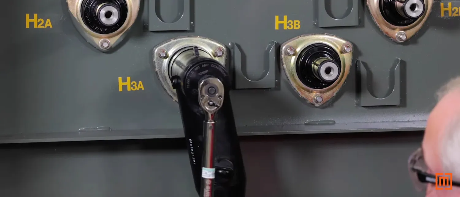
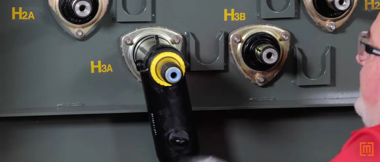
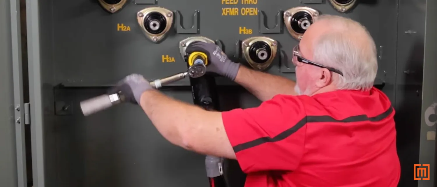
17. Attach the T-Body to Bushing
Inside the transformer, clean off the padmount bushing with cable cleaner and paper towels. Then, apply enough silicone to coat the plastic around the bushing insert. Do not apply silicone to the stud itself.
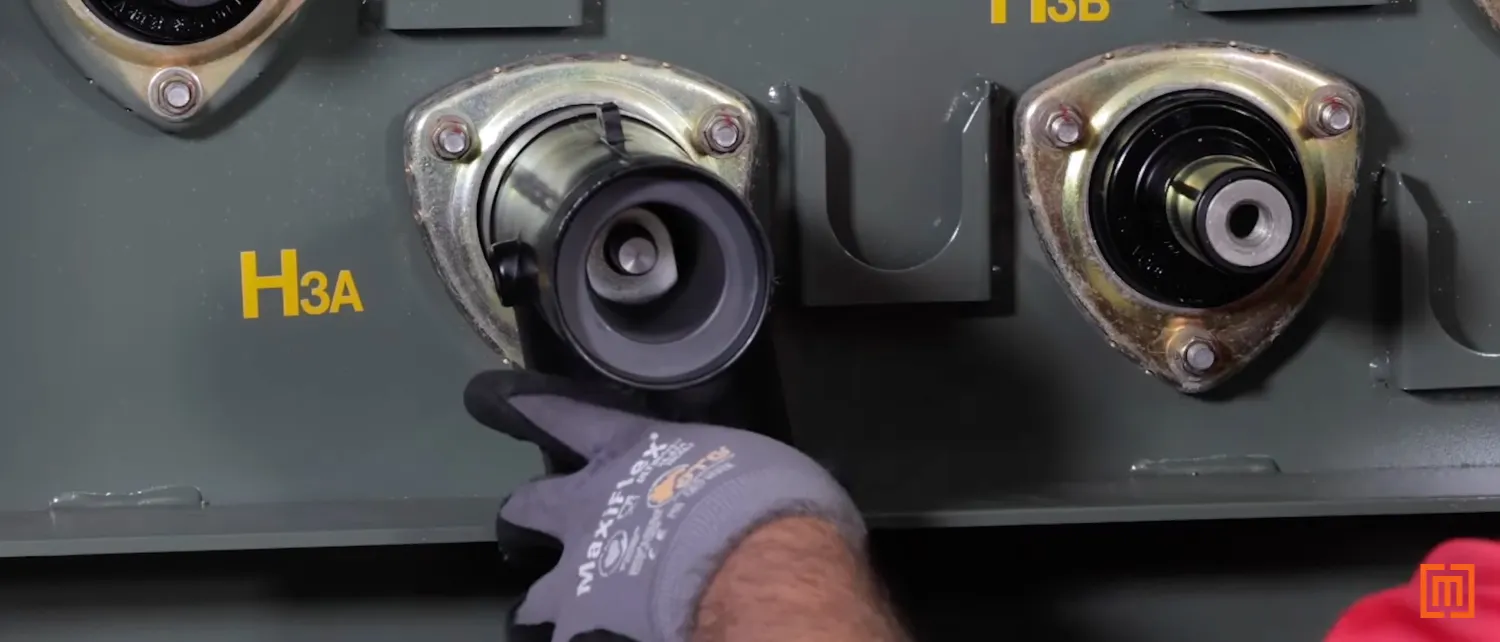
Place the T-Body on the transformer bushing. Make sure the connector lies flat against the bushing and that the stud passes through the hole in your lug.
After that, apply silicone to the inside rim of your T-Body bushing and add the cap. For a 25 kv T-Body, you should torque it to 55 foot pounds. Consult your manual for other torque specifications. Improperly torquing your T-Body is one of the leading issues that causes elbow termination failure.
18. Alternative Installation for Arresters
If your application requires arresters, you can use a 200 amp reducing tap plug instead of a T-Body cover. To install the adapter, first clean it off with paper towels. Then apply silicone around the insert section of the 200 amp adapter. Install the adapter into the 600 amp T-Body. Make sure the 600 amp side is facing the T-Body, then thread the adapter on by hand.
Then, take a 5/16 allen wrench and insert it into the 200 amp side of the adapter. Torque the wrench until the bushing is secure with 55 pounds of pressure. Finally, add an arrester or insulating cap to the 200 amp tap plug.
Follow Up
We hope you found this article helpful. At Maddox, we are your one stop shop for all your transformer needs. Check out some of our other articles if you want to learn more about transformers. If you need to purchase a transformer, we’ve got hundreds of units in stock and ready to ship. Fill out the form below to talk to one of our sales representatives today.