Guide to Transformer Windings & Coils
Wondering about the different parts of transformer windings & coils? Learn all about how windings work, different winding designs, & what's best for your unit.
December 23, 2024
Parts
What are transformer windings?
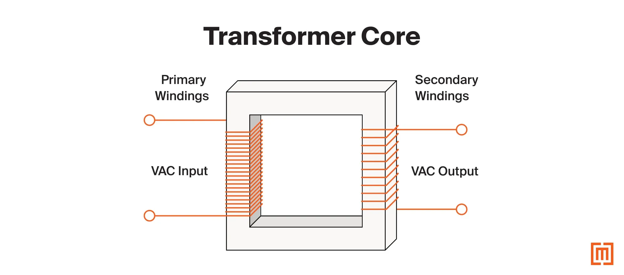
Transformer windings are coils of copper or aluminum, wrapped around the transformer’s core. They determine what voltage is produced and whether that voltage is stepped up or down.
In this article, we’ll look at the parts of a transformer’s windings. Then we’ll look at specific transformer winding designs.
Parts of Transformer Windings
Transformer coils have two main parts—a primary winding and a secondary winding. These two windings are next to each other, but are not electrically connected.
Primary Winding
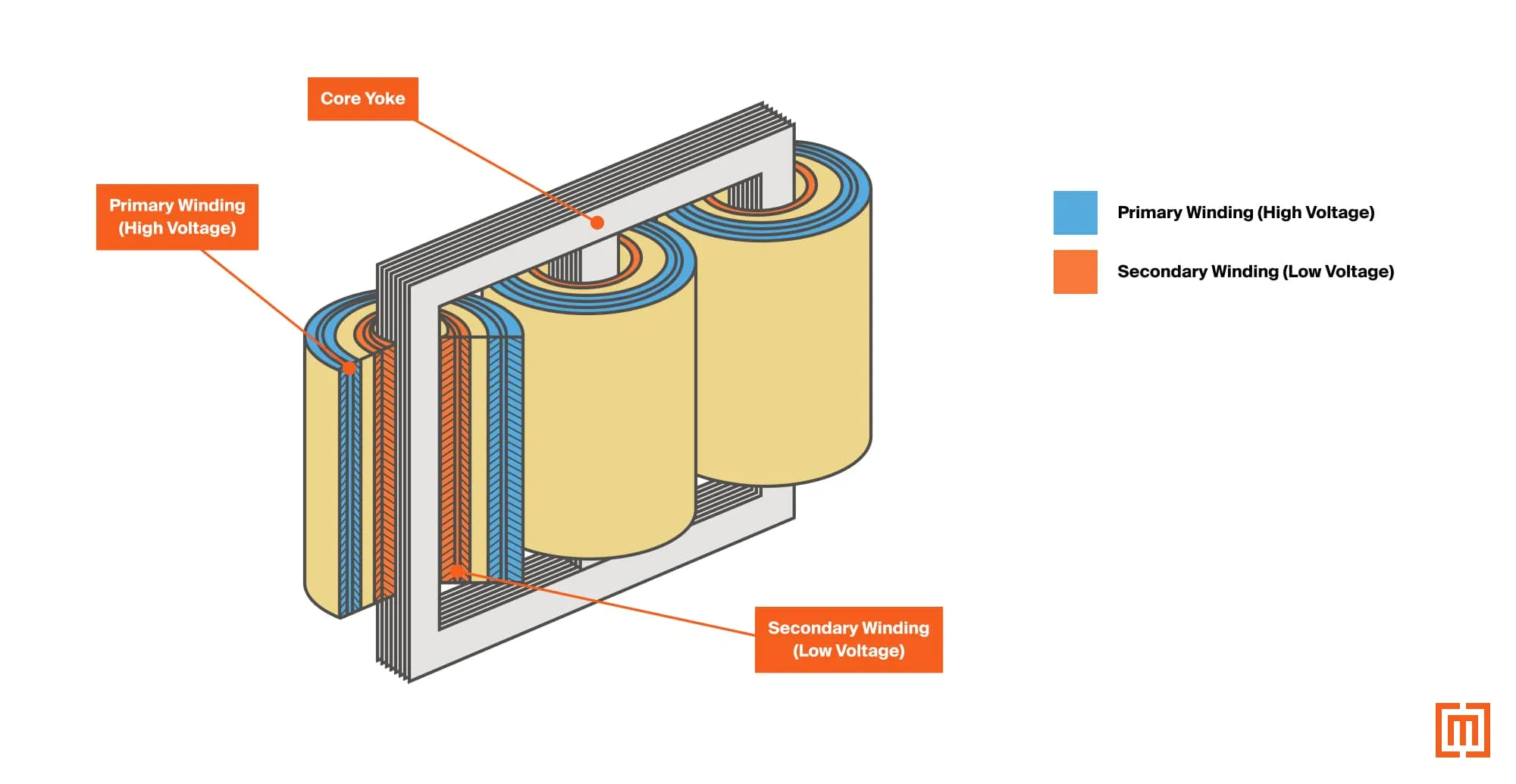
The primary winding receives voltage from the utility. The voltage adjustment taps are located on this winding. If the utility voltage is slightly higher or lower than the transformer’s nominal rating, the taps can adjust to the incoming voltage.
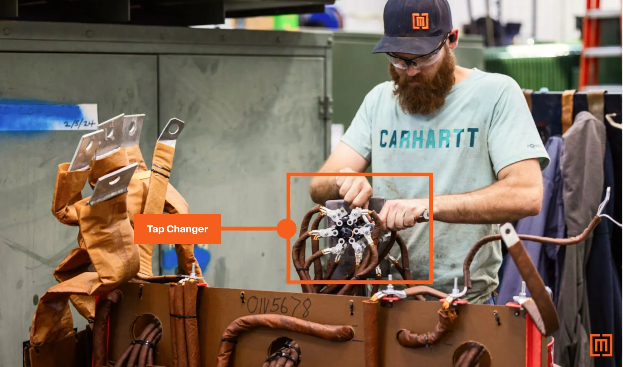
Aluminum or copper cables attach the tap leads at the winding to a tap changing device. Cable leads terminate each winding to its respective transformer bushing. The primary winding makes up the outer section of a coil.
Secondary Winding
The secondary winding steps the input voltage up or down (depending on the application). It provides voltage to loads such as factories, commercial buildings, or homes.
For distribution step-down transformers, this winding comprises the lower voltage. This section of the coil is closest to the core, requiring less insulation. Cables or bus bars connect the winding’s terminations to the transformer’s secondary bushings.
How windings work
Transformer windings operate on Faraday’s law of induction. Both windings use alternating current (AC) to produce an electromagnetic field. This field interacts with the electric circuit at the coils to produce the designated output voltage. Here’s how it works…
Applied Voltage
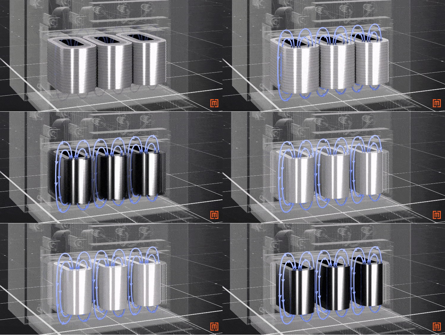
To get voltage at the secondary coil, an AC voltage is applied to the primary coil first. The alternating current (which changes direction 60 times per second), creates an electromagnetic field around the primary and secondary windings.
Induced Voltage
The electromagnetic field generated by the primary winding induces a voltage in the circuit of the secondary windings.
Ratio
The applied voltage and induced voltage values are determined by the ratio of turns between the two windings.
For example, if the primary voltage is 12,000 volts and our secondary voltage is 480 volts. That's a ratio of 25 to 1, meaning for every 25 turns in the primary coil, there's one turn in the secondary coil.
Core
The iron core strengthens the electromagnetic field produced by the coils. To reduce stray flux and maximize the voltage change, the primary and secondary are typically wound around the same core limb. Additionally, as the magnetic field activates, the metal core expands and contracts, creating the typical transformer hum or buzzing sound.
Winding Types
We will focus on two winding types–rectangular and disc windings. Rectangular layer windings are the most common for distribution transformers. For larger power class units, disc windings are used.
Rectangular Windings
Most medium voltage distribution padmount and substation transformers use rectangular windings. We’ll look at these starting from the inside of the coil and working our way out. The innermost section of the coil is made up of the low voltage conductor. With its need to carry higher current, the low voltage conductor is usually wound in large sheets.
Sheet/strip windings
Full width sheet conductor windings began in the 1950s. Using them in coil design improved short circuit strength, voltage regulation, and efficiency. They are used for low voltage coils in distribution transformers. Each layer of the winding is made up of a whole copper or aluminum sheet. Several smaller strips can also be used to make up a full sheet.
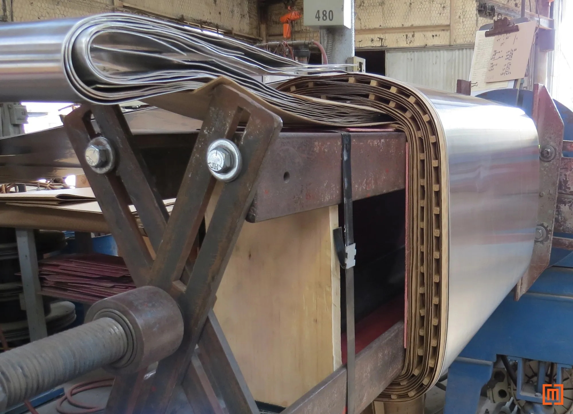
The shape of the coil is determined by a form around which the turns of conductor are wound. Each strip/sheet is interleaved with thermally upgraded kraft paper insulation. An adhesive coats the paper insulation which is activated when heated. This keeps the coil’s turns tight and compacted. When the winding is finished, it is removed with the form for fitting onto the core. The turns are numbered from inside out (starting with the one closest to the core).
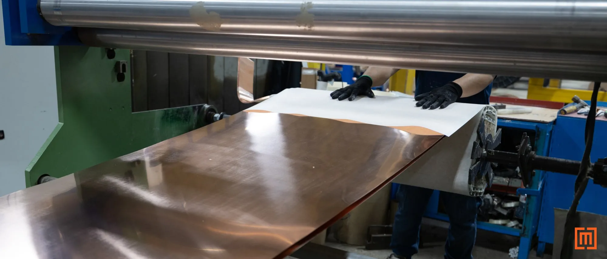
Sheet windings offer two great advantages. They offer significant cost savings. They also reduce axial short circuit forces at the coils. For this reason, vertical bracing is minimal on rectangular designs with sheet wound coils. Relegating most of the short circuit strength to the core clamp securing the winding assembly.
Layer Windings
The high voltage side windings are what we call layer-wound. The conductor for the HV winding is much smaller than the large sheets used for the LV winding. Conductors for layer windings can be round or rectangular. The common choice for distribution units is enamel coated magnet wire.
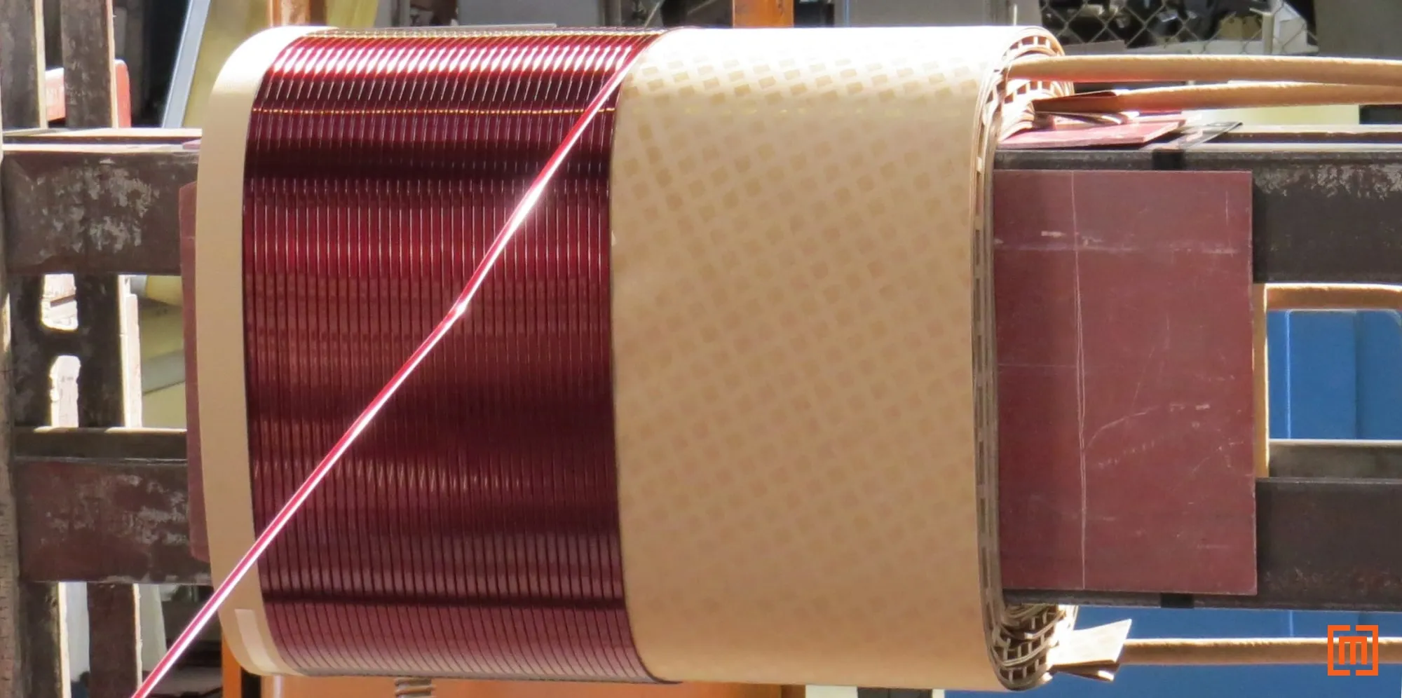
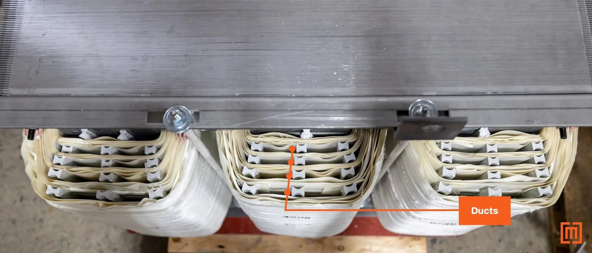
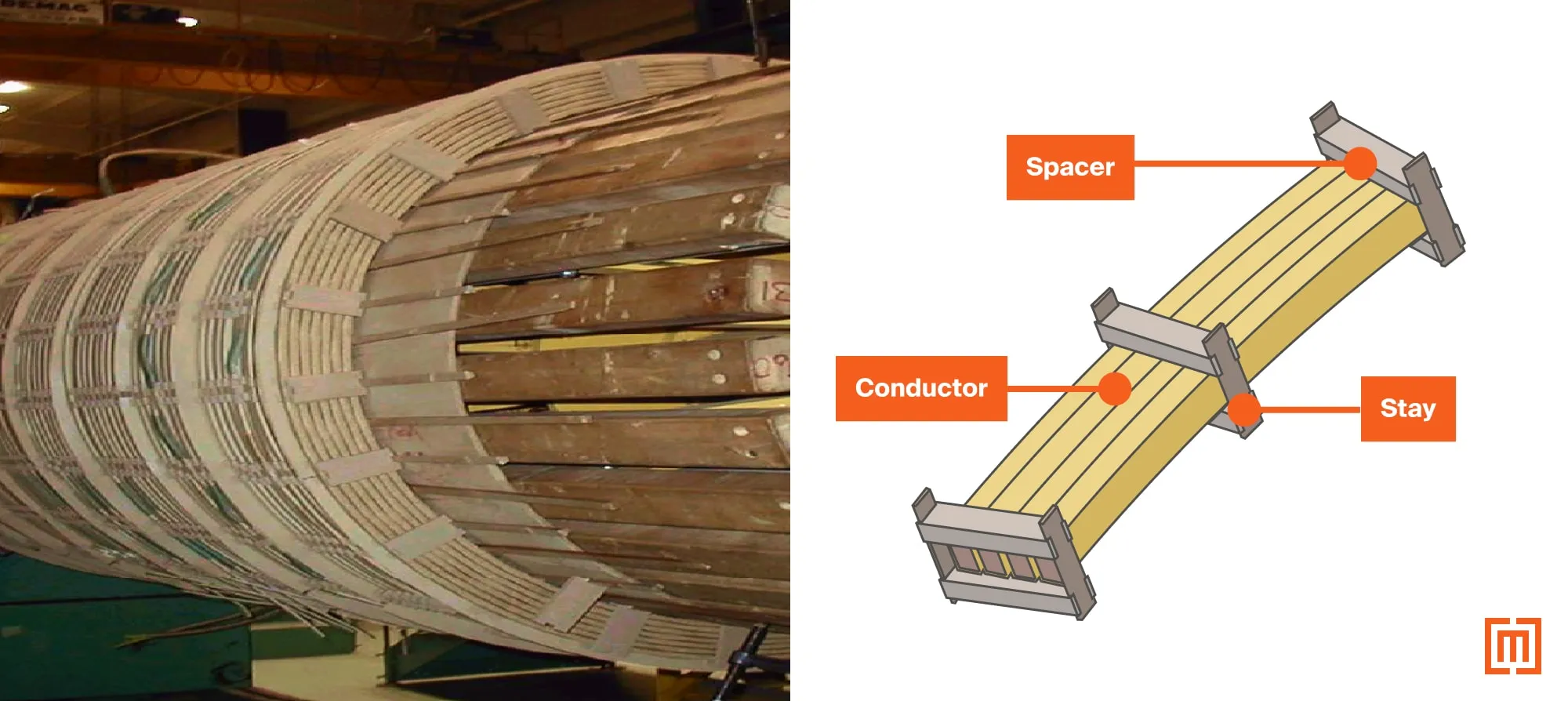
The insulated magnet wire is wound around a rectangular form from top to bottom. Once at the bottom, the conductor is then wound over the first layer all the way back to the top. Some designs will use a run-back, so the start of the next turn begins again from the top of the coil. A run-back allows each layer to be wound from the top down (rather than alternate top-to-bottom and bottom-to-top). Vertical ducts are inserted between layers for cooling.
Disc Windings
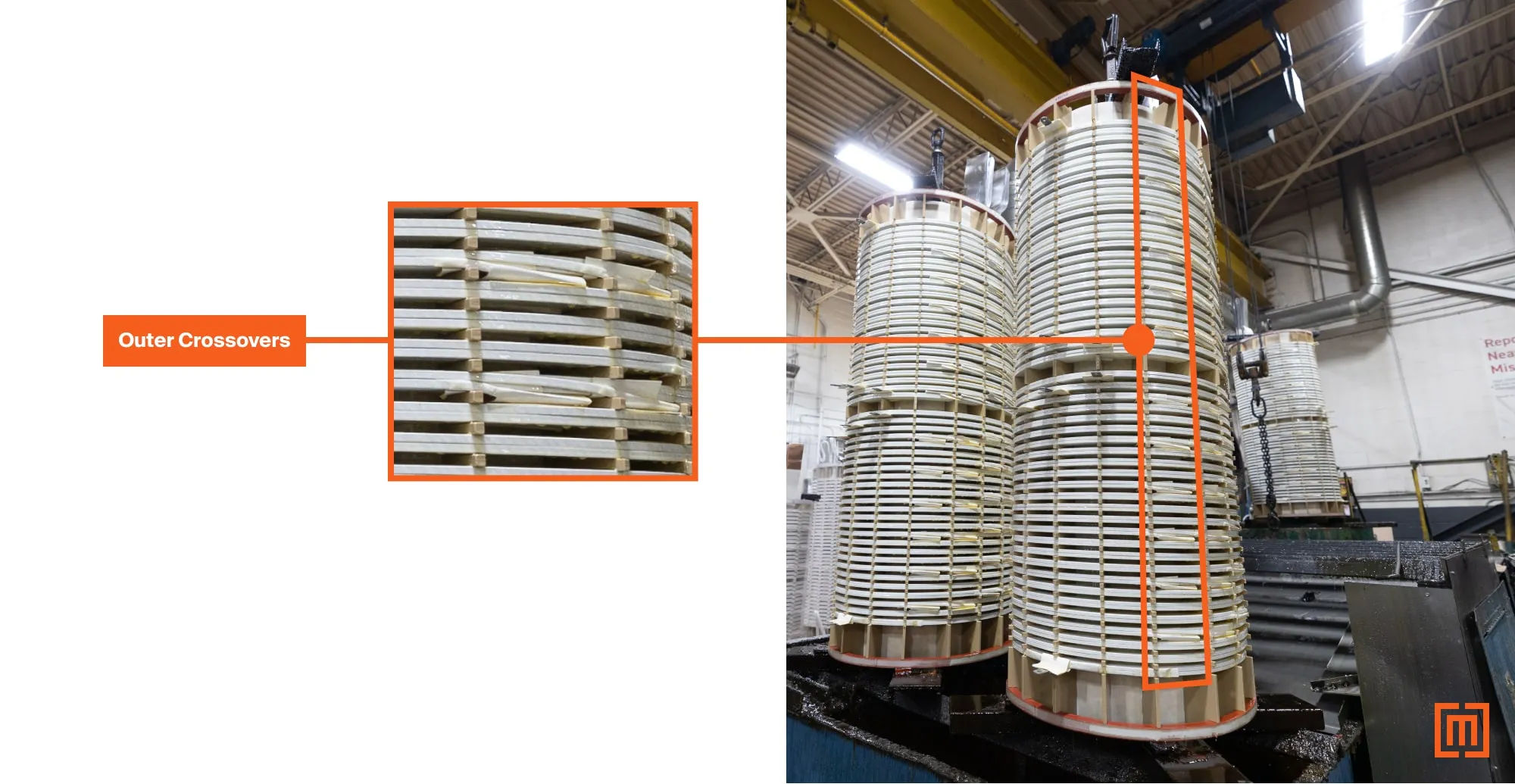
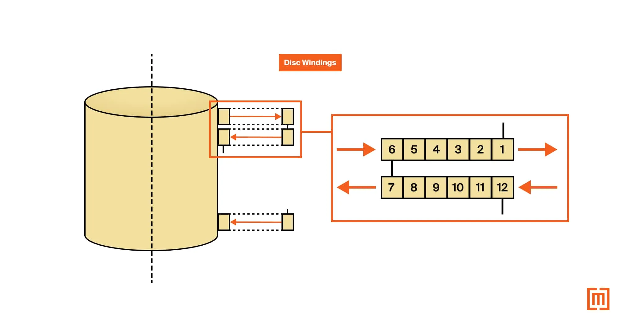
Many large power transformers are built using circular disc windings. Disk windings are usually built in a special, positive pressure regulated room, that's separate from the rest of the factory. Disc windings are made to handle the higher short circuit forces and larger impulse ratings of high voltage transformers (above 69kV). The conductors in disc wound coils form a spiral pattern, making individual discs. Once one disc is formed, a drop down (or cross-over) is used to start the formation of the second disc. For a continuously wound disc winding, the disc is wound from the inside out. Then the turns of conductor are turned over manually by hand. This allows the cross-over to the next disc to be made without splicing or braising as shown below. Special tools bend the conductor for each cross-over. This is done by hand or by automated machines.
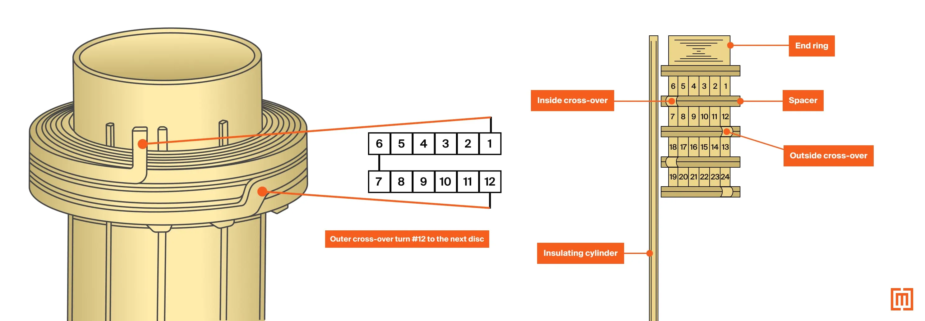
As the diagram above shows, the turns of each disk run in parallel with each other. Adding radial spacers between each disc minimizes circulating currents between these parallel turns.
You may notice each disc alternates the way the turns number from outside in (or inside out). Inside meaning nearest the core. Outside meaning the outside surface of the coil. The turn number counts from outside in with the top (first) disc. The next disc (second) down counts its turns from inside out. This configuration plays a key role in the coil’s short circuit withstand capability. Where the turns number from outside in, the short circuit forces will push inward. Where the turns number from inside out, the short circuit forces will push outward. In the event of a fault, mechanical stress displaces in two opposite directions across the coil.
Coil and Core Assembly
After the winding process, each coil is fitted onto a limb of the transformer’s core. The core style will depend on the winding type. Below is an example of a large power transformer coil lowering onto a three-limb core.
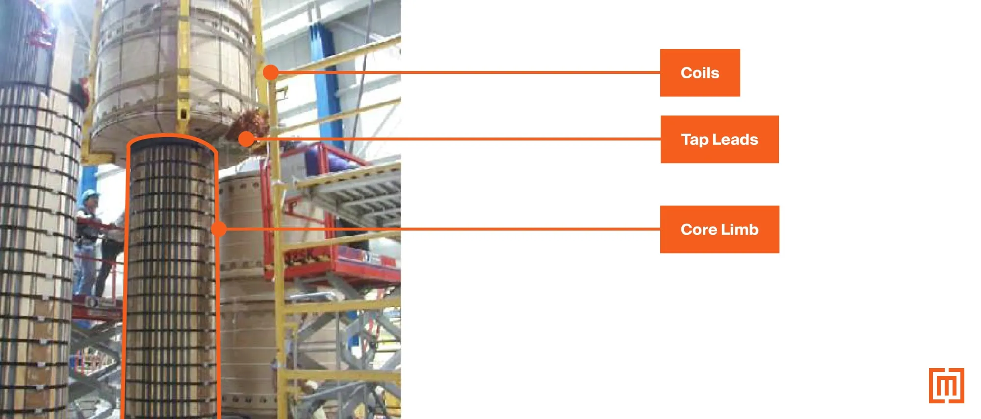
For the smaller distribution unit below, a distributed gap five-limb core is being stacked around the finished coils.
Winding Connections & Leads
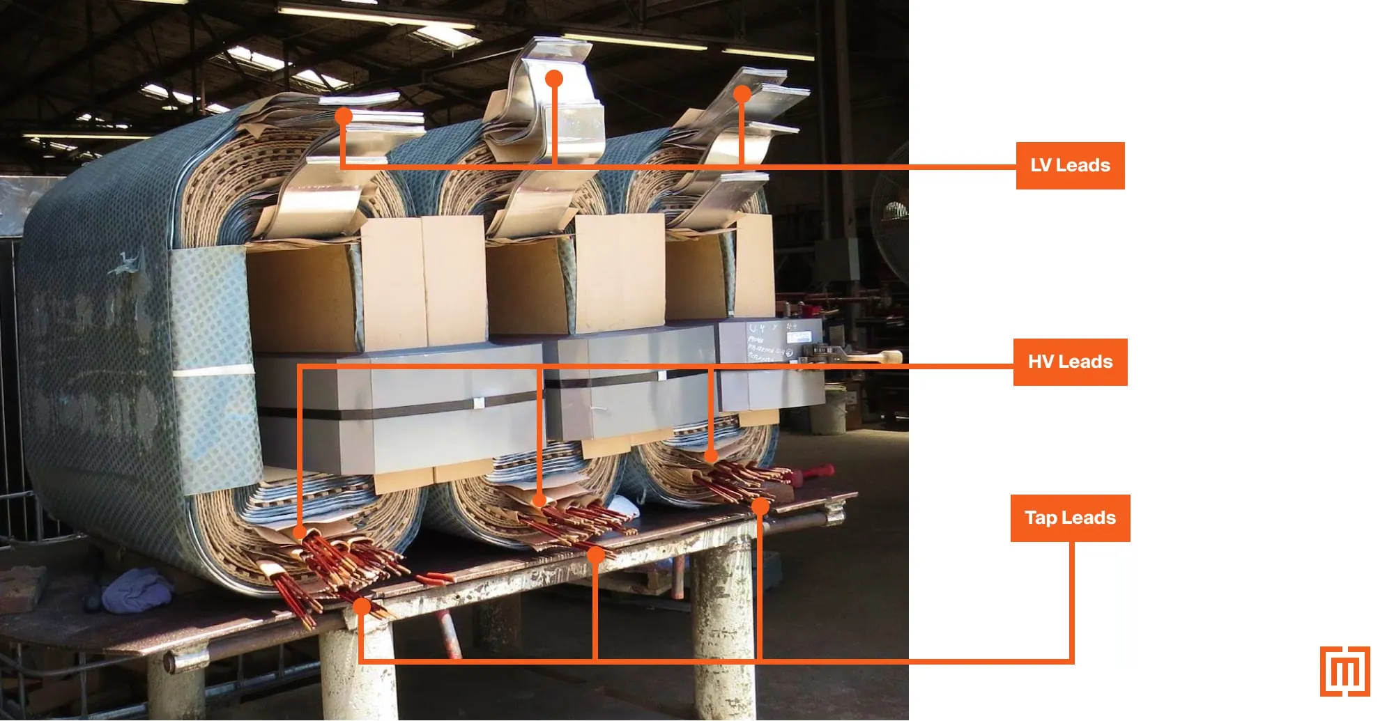
During the coil winding process, all connection points are brought out to be terminated. These connection points include the primary and secondary winding leads and the voltage adjustment tap leads. The tap connections and coil leads are labeled and prepped for termination later.
Once assembled around the core, make up of all termination points begins. The connections may be made with cable or bus. Lower voltages with higher current will typically use bus. Higher voltage applications with lower current utilize cable connections.
Making Connections
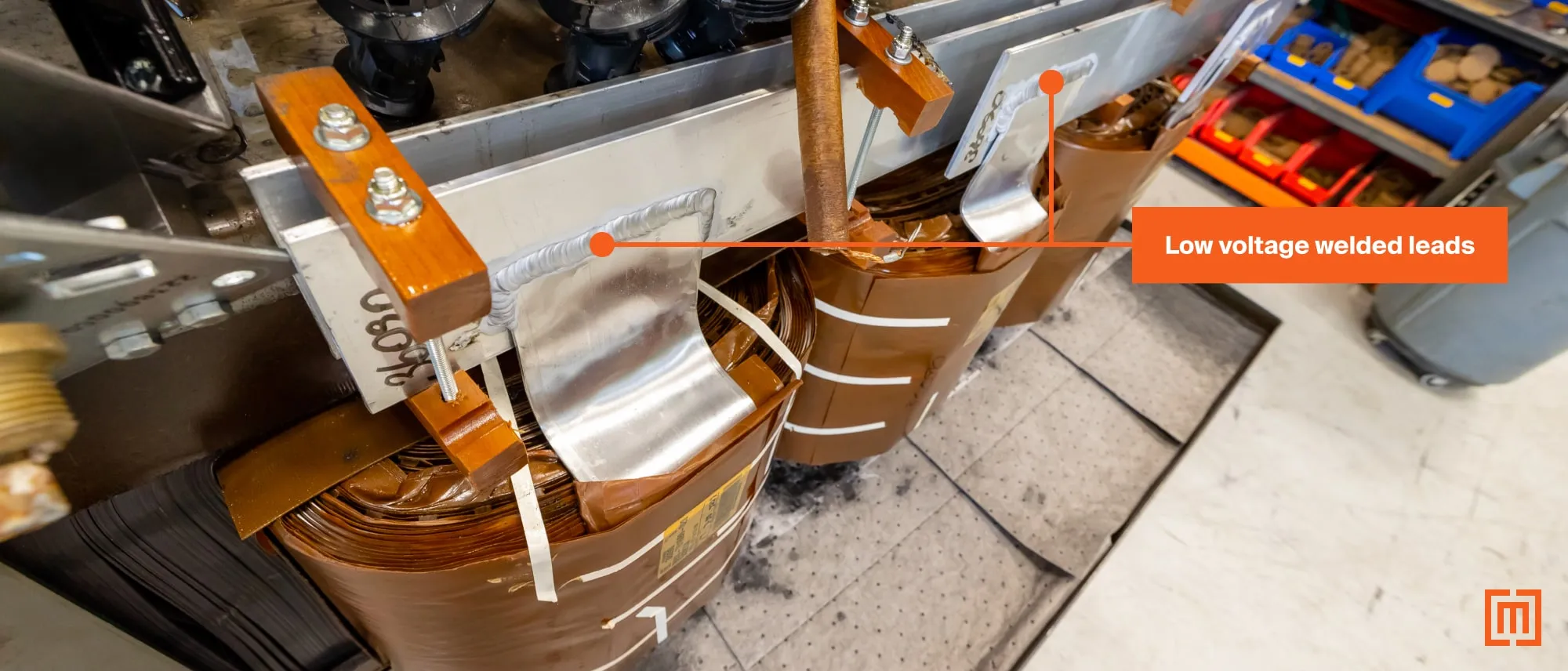
Copper or aluminum conductors make up these connections (depending on the winding conductor). The primary and secondary leads brought out of the coils are welded or brazed. Due to the higher temperatures required for welding copper, braising is the more common option.
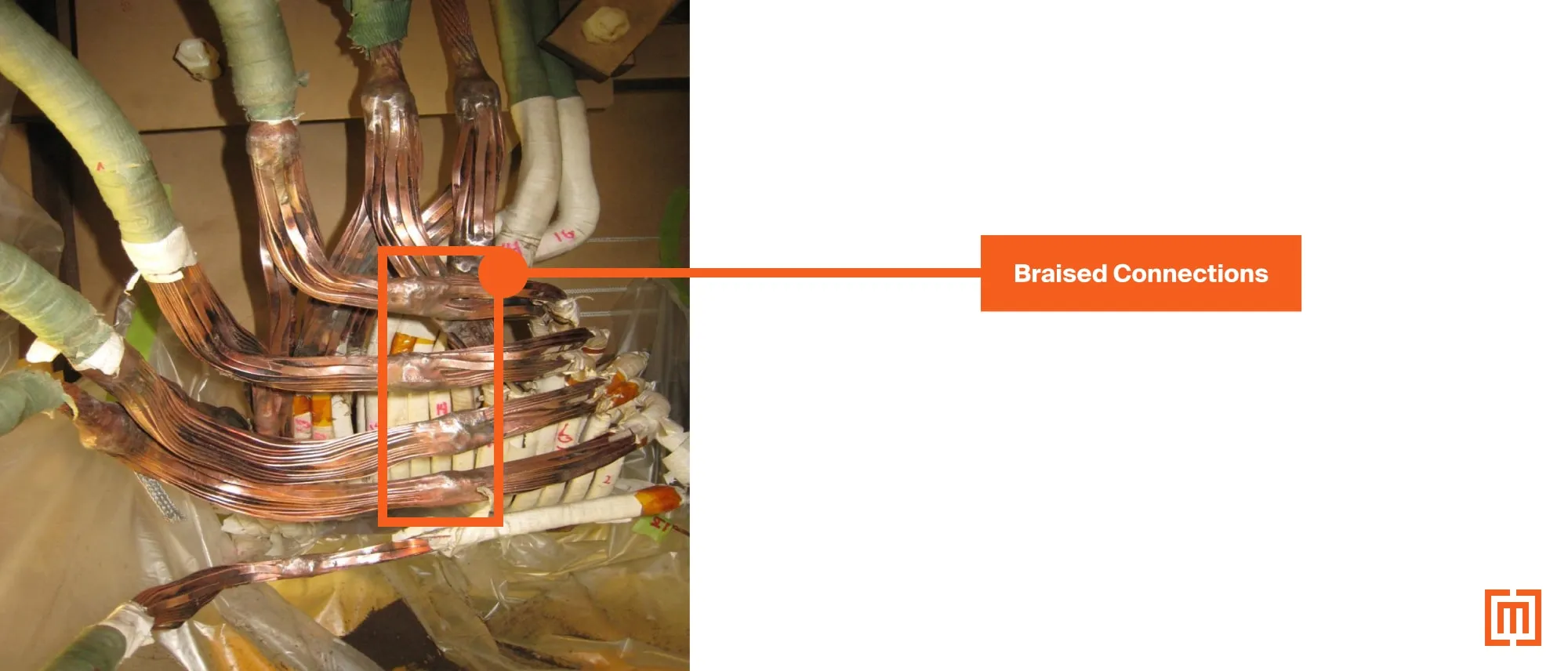
Aluminum welds together more easily at lower temperatures. Welded terminations are more common with aluminum.
Terminations to Devices & Bushings
The primary winding leads are brought out for making permanent connections to the bushings. The HV leads are usually cable connected. The secondary winding leads terminate at the low voltage bushings. For distribution transformers, connections terminate with hard (or flexible) bus or cable.
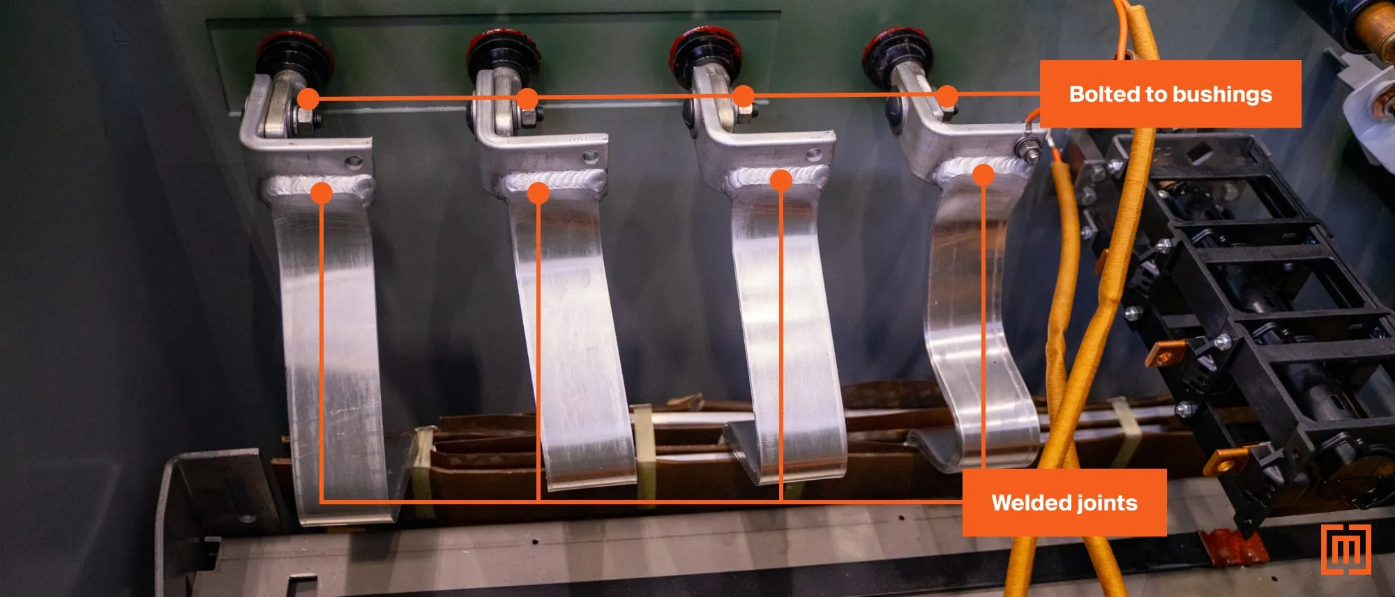
Connections between the winding leads and devices are made with bolted or crimped connections. Once terminated, the tap leads run to the tap changing device.
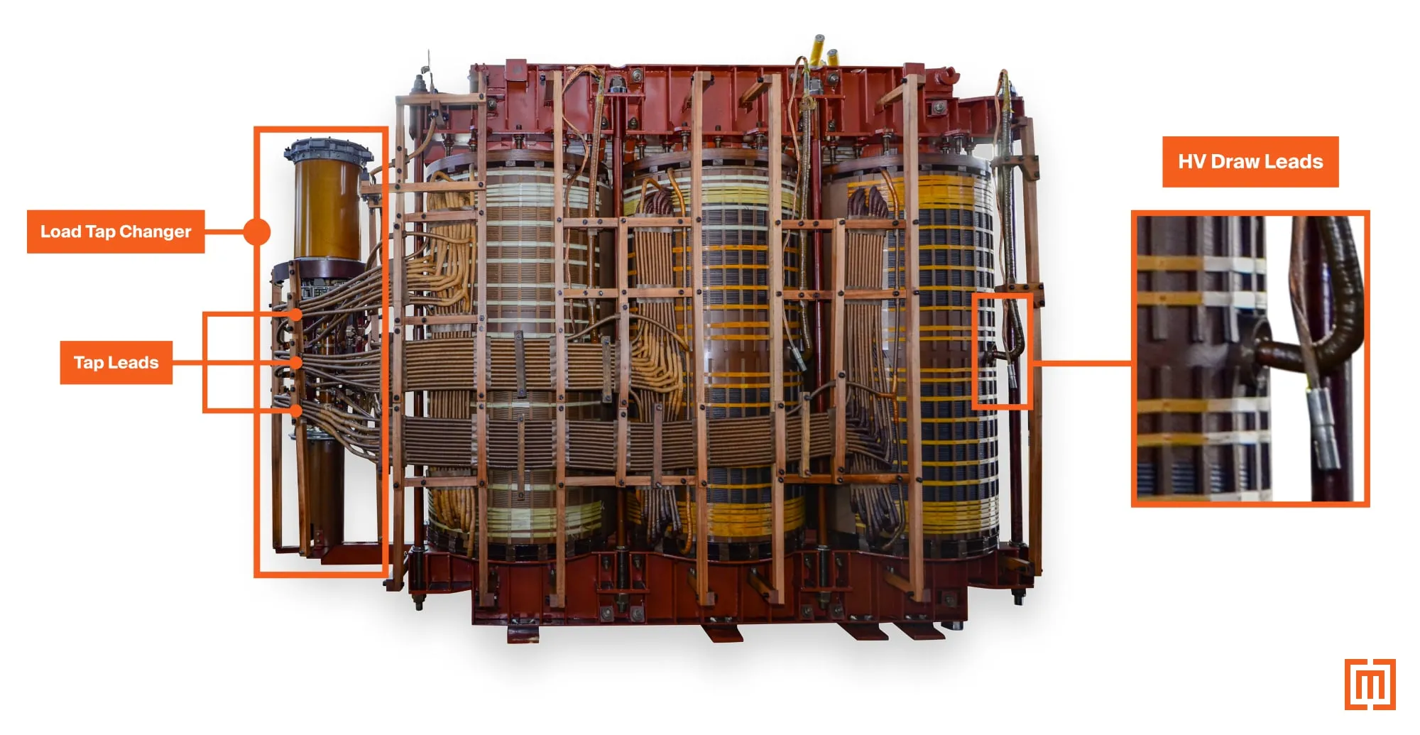
For larger transformers with bushings requiring field installation, a draw lead may be brought out. The picture below shows three draw leads for the primary bushings. The tap leads run to a load tap changing (LTC) device.
Which winding type: circular vs. rectangular
When choosing between rectangular and circular transformer windings, several factors come into play, including cost, efficiency, and voltage capacity.
Rectangular
One of the most significant benefits to a rectangular design is cost. The typical five-leg distributed gap wrapped core design with rectangular layer HV and sheet LV wound coils is simple to construct, lower cost to build, has high efficiency, and offers a reliable service life. This makes it the obvious choice for distribution applications. The reduction of axial short circuit forces from the sheet wound LV coils also allows this design to be used in larger applications as well. Design improvements and short circuit testing show their usefulness at sizes up to 20 MVA (69kV and below).
Circular Disk
Though they cost more, circular disc designs offer larger short circuit withstand capability. This is why they are used exclusively on larger power units above 20 MVA. Transformer windings above 69kV use disk windings as a rule. The unique features of disc type windings make them suited for voltage requirements up to 550kV BIL.
But, winding the coils of a circular disk design is far more labor intensive and costly. The build time is also longer.
The low cost, quicker build time, and high efficiency ratings available for layer wound rectangular designs make them ideal for medium voltage transformers 35kV and below. For higher voltage applications above 69kV, disc wound units are the go to choice.
Conclusion
Maddox stocks transformers in both winding configurations for a variety of projects and applications. Our technical support staff is ready to work with you on your project for whichever winding style you require. Fill out the form below to get started.


