Pad Mounted Switchgear Manual

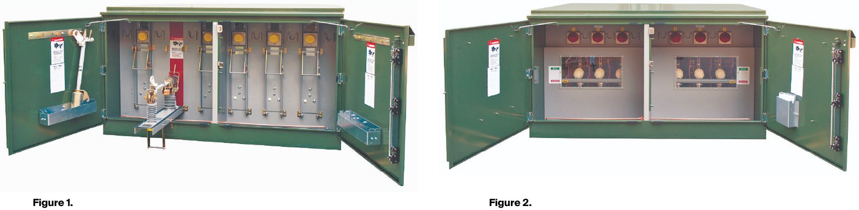
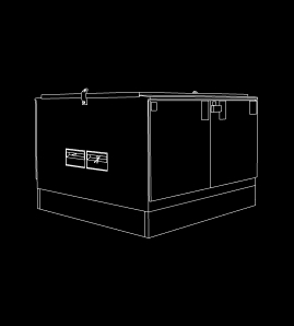
Figure 1. Fuse compartment of Maddox MIT-PMSW pad-mounted switchgear. Spacing between fuse panels is adequate to accommodate a horizontal feed-thru standoff bushing—and there is a viewing window directly in front of each fuse, making blown-fuse targets fully visible. Doors feature three-point automatic, self-latching door latches. The captive security bolt rotates 60° in either direction (clockwise or counter-clockwise) to open. Do not use power tools. See page 4 for additional information.
Figure 2. Switch compartment of Maddox MIT-PMSW pad-mounted switchgear. Storage for fuse assemblies is on fuse side, better facilitating fuse changing procedures. Wide-view windows and broad blades provide improved visibility to make it easier to verify switch position, even behind cables and elbows, while the open/closed labels serve to further enhance this user-friendly design.
QUALIFIED PERSONS
WARNING: The equipment covered by this publication must be selected for a specific application and it must be operated and maintained by Qualified Persons who are thoroughly trained and knowledgeable in the installation, operation, and maintenance of underground power distribution equipment along with the associated hazards that may be involved. This publication is written only for such qualified persons and is not intended to be a substitute for adequate training and experience in safety procedures for this type of equipment. Proper installation is the responsibility of the operating and construction personnel and the utility performing and authorizing the work. Completion of these instructions implies no further warranty by the manufacturer.
A Qualified Person is defined in the National Electrical Code (NEC/NFPA-70) as:
One who has skills and knowledge related to the construction and operation of the electrical equipment and installations and has received safety training to recognize and avoid the hazards involved.
The specific electrical safety training requirements to be considered a qualified person are detailed in NFPA-70E, Article 110.1(D), Employee Training. Some of the requirements from the 2012 edition are shown below. For the specific detailed training requirements for a Qualified Person make certain to refer to the most recent applicable edition.
These training requirements would include, but are not limited, to the following key points:
- The skills and techniques necessary to distinguish exposed energized parts from other parts of electrical equipment.
- The skills and techniques necessary to determine the proper approach distances corresponding to the voltages to which the qualified person will be exposed.
- The proper use of the special precautionary techniques, personal protective equipment, insulating and shielding materials, and insulated tools for working on or near exposed energized parts of electrical equipment.
- Tasks performed less often than once per year have additional training requirements.
These instructions are intended only for such qualified persons. They are not intended to be a substitute for adequate training and experience in safety procedures for this type of equipment. Additionally, the recommendations in this instruction bulletin are not intended to supersede or to take the place of established utility safety guidelines and established practices. If there is any question, consult with your foreman or supervisor, as appropriate.
Please refer to OSHA 29 CFR 1910.399 and NFPA 70E Articles 100 and 110.
SAFETY INFORMATION
Understanding Safety-Alert Messages
There are several types of safety-alert messages which may appear throughout this instruction bulletin as well as on labels attached to the pad-mounted switchgear. Familiarize yourself with these types of messages and the importance of the various signal words, as explained below.
DANGER indicates a hazardous situation which, if not avoided, will result in death or serious injury.
WARNING indicates a hazardous situation which, if not avoided, could result in death or serious injury.
CAUTION indicates a hazardous situation which, if not avoided, could result in minor or moderate injury.
NOTICE is used to address practices not related to physical injury.
SAFETY INSTRUCTIONS (or equivalent) signs indicate specific safety-related instructions or procedures.
SAFETY PRECAUTION
DANGER: Maddox Fuse Mountings in conjunction with appropriate fuses are designed to protect equipment and to disconnect faulted equipment from the system. The fuses cannot protect personnel from injury or electrocution if contact is made with energized circuits or hardware.
FOLLOWING SAFETY INSTRUCTIONS
NOTICE: Thoroughly and carefully read this instruction bulletin before installation of the pad-mounted switchgear, before switching or operating the switches or fuse mountings in this equipment, and before performing any maintenance on the equipment.
INTRODUCTION
Type MIT-PMSW pad-mounted switchgear is designed to provide dependable on-the-line service and to make installation, operation and maintenance as simple as possible.High quality materials and careful workmanship have been combined to provide the best switchgear available. The switchgear has been thoroughly inspected and adjusted at the factory. However, successful operation depends on proper installation and care.
This manual has been written to assist you in obtaining long and economical service from your switchgear.
Read this manual before installing and operating your switchgear.
Receiving
Upon receipt of the switchgear, check each item received for shipping damage. Each item should be checked against the shipping manifest to assure that the proper number of items were received. Should any shortage or damage exist, note it on the shipping papers. A claim should be filed at once with the carrier and the Maddox agent or sales office should be notified.
Handling
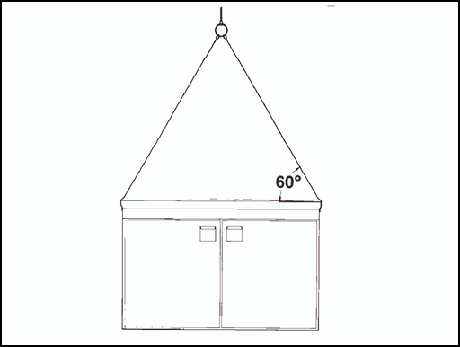
Removable lifting plates are provided to allow the use of hooks to lift the complete enclosure. The lifting device should be arranged to evenly distribute the lifting force between the lifting plates.
CAUTION: Do not lift at an angle less than 60° from the horizontal. See Figure 3. A spreader bar may be required to maintain proper angles. Failure to comply with this requirement may result in damage to the equipment.
The switchgear is securely mounted to a sturdy shipping pallet with provisions for forklift use. The use of a forklift truck is not recommended, but if this method is used the forks must extend completely through the skid to avoid damaging the equipment.StorageThe switchgear as received may be wrapped in a protective plastic film.
NOTICE: To avoid damage to the enclosure finish, the protective film must be removed for outdoor storage of unit.Export or special packing is available as an option based on customer’s requirements and special conditions. Separate instructions are available for these situations.
GENERAL DESCRIPTION
Type MIT-PMSW deadfront pad-mounted switchgear consists of one or more three-pole, single-throw, gang-operated, quick-make, quick-break, load interrupter switches that may be used in combination with one or more three-phase sets of single-pole fuse mountings. Switches are typically equipped with 600-ampere bushings to accommodate 600-ampere elbow connectors. Fuse mountings are equipped with 200-ampere bushing wells to accommodate 200-ampere loadbreak (or non-loadbreak) inserts and elbows. When used in conjunction with power fuses, expulsion or current-limiting type, and other protective devices, the MIT-PMSW switchgear provides a secure and efficient means of 3-pole switching on main feeders and circuit protection with single-pole switching of elbows on load feeders.
SECURITY FEATURES
Type MIT-PMSW pad-mounted switchgear incorporates a number of security features to minimize hazards to operating personnel.
1. Rugged 11-gauge steel, braced by all welded construction of the enclosure, roof, and doors assures a tamper-resistant design.
2. Padlockable switch operating pocket handles and doors with security bolts provide customer-controlled access.
3. Switch position indicators verify positive switch position.
4. Provisions to padlock switch in open or closed position provide user controlled switch operation (optional).
5. Key interlocks to ensure a pre-determined sequence of mechanical operations (optional).
6. Hazard-alert signs and labels, both external and internal, which indicate potential hazards to personnel.
CAUTION: Do not use power tools to operate the security bolt.
AUTO-LATCH DOOR
Active Door (“Auto-Latch Door”)
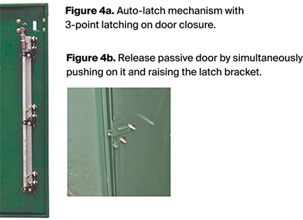
The type MIT-PMSW pad-mounted switchgear incorporates an active door, which includes an automatic three-point latching system for enclosure security. The features and operation of the auto-latch active door are discussed below. See Figure 4a.
Passive Door
The passive door is overlapped by the active door, ensuring that the auto-latch mechanism must first be released before accessing the passive door. Once so accessed, the passive door is released by raising the latch bracket from its engaged (latched) position. See Figure 4b.
Features of the Auto-Jet Mechanism on the Active Door
The automatic door latching feature furnished on the active doors provides ease in opening and closing of the doors. Features of the Auto-latch system are:
- Automatic 3-point latching upon door closure (see Figure 4a). After opening, the door is automatically set for latching upon door closure.
- Unlatching is only accomplished by an unrestrained rotation (approximately 60° in either direction) of the captive pentahead or hexhead actuator bolt.
- The door padlocking provision prevents unlatching the mechanism until the padlock has been removed. Padlocking secures the door to the cabinet enclosure.
- A stainless steel protective cover guards the padlock from tampering. Also, access to and visibility of, the actuator bolt is only possible after the padlock has been removed.
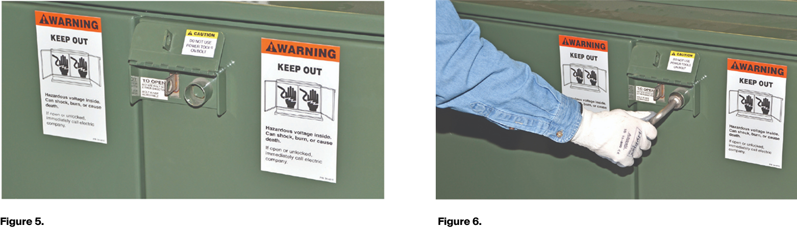
Figure 5. Raise cover to access security bolt. Review and understand the “CAUTION” label on the underside of the cover.
Figure 6. Use a manual wrench with pentahead or hexhead socket as applicable. As explained on the caution label, DO NOT USE POWER TOOLS. Rotate the security bolt clockwise or counter-clockwise to release three-point latch and charge for subsequent door closing. Do not use power tools to operate the security bolt.
Auto-Latch Door Operation
Opening:
1. Remove padlock and raise protective cover exposing security bolt. See Figure 5.
2. If equipped with the standard pentahead security bolt, use the standard pentahead socket (or if equipped with an optional hexhead bolt, use a 3/4” hexhead socket) to rotate the captive actuator bolt head approximately 60° in either direction until the latching mechanism has tripped, releasing the door. Do not use power tools to operate the security bolt. See Figure 6.
3. Open the active door. Open the passive door by simultaneously pushing on it and pulling up on the latch bracket. See Figure 4b. Secure the doors with the doorkeepers.
Closing:
1. Replace or release door keeper and close and secure latch bracket onto passive door. Then, release and replace door keeper and secure the active door by firmly and briskly pushing it closed. Mechanism will automatically latch.
2. Install padlock through protective cover tab and enclosure tab.
INSTALLATION
Each unit is shipped with this instruction bulletin, which is located inside the switch compartment door. These instructions should be reviewed prior to placing unit on pad.
NOTICE: Installer shall provide appropriate clear working space, as required by applicable codes and/or work practices, to allow installation, operation, inspection, and maintenance of the switchgear.
PLACEMENT OF UNIT
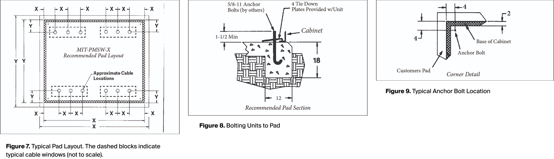
Remove unit from shipping pallet per handling procedures on Page 2 (see Figure 3). When unit has been correctly oriented and placed on pad (see Figure 7), verify that unit is level and shim if necessary between unit base and pad. Secure unit to pad using four (4) tie-down clips as furnished (see Figures 8 and 9). Check compartment door operation for any binding due to enclosure distortion and re-shim if necessary. A recessed grouting should then be applied between unit base and pad to prevent entry of foreign objects and moisture.
BUSHINGS AND BUSHING WELLS
Switch Compartments and Terminal Compartments are equipped with 600A bushings conforming to the interface requirements of IEEE-386 (IEEE Standard for Separable Insulated Connector Systems for Power Distribution Systems Rated 2.5 kV through 35 kV).
- In addition, there may be optional parallel 600A bushings or parallel 200A bushing wells.
The fuse compartments are equipped with 200A bushing wells, which conform to the interface and bushing well stud requirements of IEEE-386.
- Due to the configuration and operating characteristics of the MIT-PMSW fuse panels, 600A bushings and/or parallel bushings or bushing wells are not provided on the fuse panels.
Bushings Inserts
When 200A bushing well inserts are to be installed into 200A bushing wells, it is important to follow the instructions provided with the bushing insert.
1. The installation instructions for the bushing insert will provide the required information for lubricating the component interfaces and the appropriate torque values for installation.
2. Do not exceed the stated torque values when installing the bushing insert, while always using the proper torque tools and methods.
- IEEE-386 calls for the bushing well stud to withstand a minimum torque of 17 ft-lbf (23-N-m) without stripping or fracturing.
- In some cases, even “hand-tight” may damage the IEEE-386 conforming 200A studs.
CAUTION: Always follow the recommended lubrication processes and torque specifications when installing bushing well inserts. Failure to follow these instructions may lead to mechanical and/or electrical damage.
CUSTOMER CABLE CONNECTIONS
1. Make up the primary cable connections per user’s standard URD operating procedures, cable manufacturer instructions, and elbow terminator manufacturer instructions.
CAUTION: When terminating cables in dead-front switchgear, ensure that each cable termination connector lays flat against the corresponding flat copper contact surface of the associated bushing, prior to making up the elbow, so that no additional strain is put on the bushing. The connecting hardware and components of dead-break T-body elbows are not to be used to pull the cable terminations into alignment with the bushings.
2. Connect the concentric neutral wires to the enclosure ground pads inside enclosure to facilitate ground system conforming to user’s grounding procedures.
WARNING: The maximum momentary rating of the switchgear must be considered when selecting cable size for connecting switchgear to system ground. Refer to unit rating plate.
3. Install fault indicators, if applicable.
4. Fuse Compartment Cable Positioning
- Cable connections to the loadbreak fuse mounting terminals must be fed through the cable guides, which are located under the parking stands. This is required to permit the proper operation of the pivoting fuse mountings.
- Each cable guide may be rotated or temporarily removed to facilitate cable installation, so long as it is returned to its original orientation, under its corresponding parking stand, after the cables are installed.
WARNING: Before energizing the switchgear, remove all yellow and red shipping caps on bushings and bushing wells, and replace them with a suitable system of insulated separable connectors (elbows), insulating protective covers, or plugs, as appropriate. Failure to replace the shipping caps may result in flashover, equipment damage, serious personal injury, or death.
SWITCH DESCRIPTION
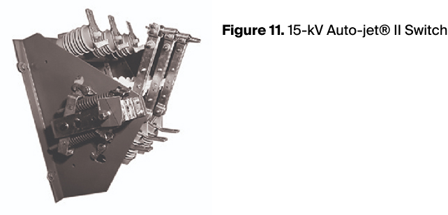
The Auto-jet® II switch provides a unique method of load interruption, producing a laminated jet of air which extinguishes the arc.
Auto-jet® II switches have a heavy gauge steel, all welded base frame that assures proper alignment and eliminates any problem with switch-to-enclosure alignment. A quick-make, quick-break stored energy mechanism with heavy duty, long life die springs provides high speed opening and closing independent of the operating handle speed.
PAD RECOMMENDATIONS
1. The generic (or top-level) drawings show the recommended positioning for the incoming cable at the switch and fuse terminations, as appropriate, along with the footprint of the switchgear.
2. The use of box pads (or equivalent) with a cable chamber or “pit” is recommended for maximum flexibility in cable installation andmanagement.
3. Full openings or slotted openings (“cable windows”) are especially desirable for slab-on-grade installations which do not have a cable chamber or pit.
4. The following pad construction techniques have proven problematic and are not recommended:
- Embedded ducts in poured concrete slab-on-grade installations when the ducts are not installed in the recommended locations.
- A single duct in slab-on-grade construction for multiple phases, especially if the duct extends any appreciable distance above the pad-top.
- Note - Some of these issues may be alleviated by installing a base spacer. Contact the factory for details if needed.
SWITCH OPERATING SEQUENCE
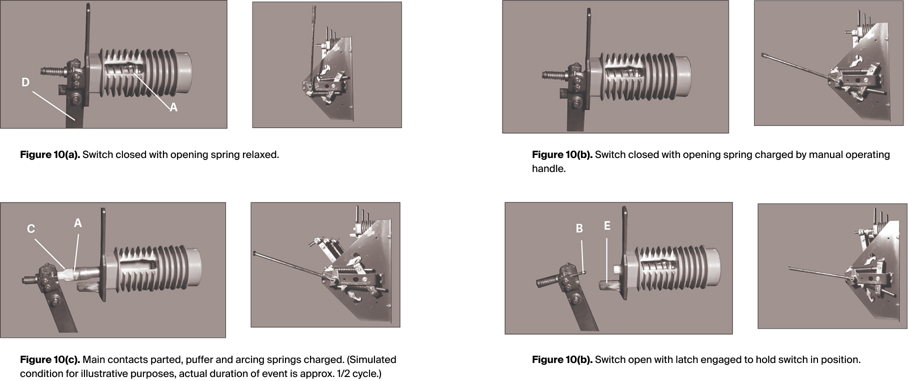
The operating sequence of the Auto-jet® interrupter is pictured in the left-hand column in Figures 10(a) through 10(d) and the corresponding positions of the switch and its mechanism are pictured in the right-hand column. The Auto-jet® interrupter consists of a piston (A) mounted in the cavity of the upper insulator. The movable arcing probe (B) engages a tulip contact (C) inside the piston. As the switch blade (D) is pulled open by the stored energy mechanism, the blade separates from the main-contact stab (E). The piston is pulled forward by means of the movable arcing probe, which compresses a heavy gauge spring encircling the piston and a spring encircling the arcing probe. At the end of its travel, the piston is released from the arcing probe and, under the action of the heavy spring, is rapidly pushed backward into the cavity. This travel produces a jet of laminated compressed air up through the center of the piston, which extinguishes the arc. The spring encircling the movable arcing probe rapidly retracts the probe and increases the speed of separation, which prevents restrike. All of this action is in addition to the spring energy transmitted to the switch blades by the quick-make quick-break mechanism of the switch.
*The three-time duty-cycle fault-closing rating means that the switch can be closed three times into rated fault amperes and remain operable and able to carry and interrupt its rated load current.
Ratings of the pad-mounted switchgear assembly are based on the lowest ratings of the components furnished. Refer to ratings labels on the interior of the compartment doors.
OPERATING THE AUTO-JET® II SWITCH
1. Remove padlock and open the switch lockbox access cover. (See Figures 12 and 13.)
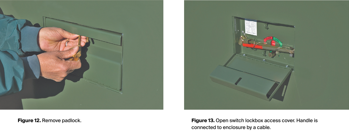
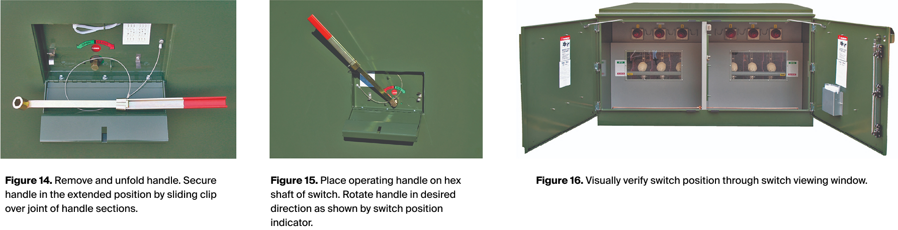
2. Remove switch operating handle from storage clips. Unfold the handle and secure in the extended position by sliding the clamp over the hinged section (see Figure 14). Place the handle on the hex switch-operating shaft (see Figure 15). If provision to padlock switch in open or closed position is provided (K2 option), the additional padlock (if installed) must be removed before access to hex switch-operating shaft can be accomplished. If key interlock(s) are provided (K1, K3 or K4 options), switch may be locked in the open position.
3. Rotate handle in the direction as indicated on the label to open or close switch. Verify switch position by observing the switch position indicator in the handle pocket and by inspecting the switch through the viewing window provided in each switch compartment. (See Figure 16.)
4. Remove handle from hex shaft, fold it for storage and place in the correct orientation on the clips for storage.
5. Close switch lockbox access cover and padlock.
CAUTION: Access cover should be padlocked whenever switchgear is left unattended.
6. Switch position should be visually verified by opening access door of switch compartment and checking actual switch position through viewing window. See Figure 16.
FUSE DESCRIPTION
The MIT-PMSW pivoting fuse mounting provides a convenient means to install fuses during initial energization as well as during fuse replacement. The fuse mounting includes an interlocking latch that prevents access to fuses unless the elbow connector is removed, while also providing a convenient means to unlatch and lower the fuse mounting.
The MIT-PMSW fuse mountings include a heavy gauge formed channel base with viewing windows to observe the blown fuse indicator. A GPO-3 fiberglass barrier blocks access to the interior of the MIT-PMSW unit, precluding exposure to high voltage, while the fuse mounting is lowered. When the fuse mounting is in the lowered position, the fuse is completely de-energized and isolated from high voltage. A locking bracket secures the fuse mounting to the door stile, facilitating fuse removal.
FUSE REMOVAL
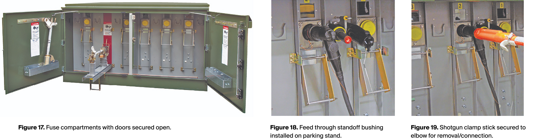
1. Open appropriate fuse compartment door and secure with the wind stop. See Figure 17.
2. Install the grappler tool on the universal head of the shotgun clamp stick.
3. Using the shotgun clamp stick, install the feed-through standoff bushing on the parking stand. See Figure 18.
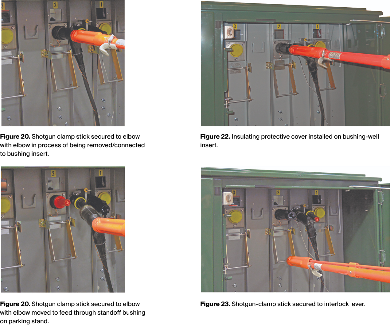
4. If appropriate for operating circumstances of the system, test the elbow to be moved for voltage. After verifying that voltage is not present, use the shotgun clamp stick to remove the elbow connector from the appropriate bushing well, following standard system operating procedures and the elbow manufacturer’s instructions. Move the elbow connector onto a standard feed-thru standoff bushing that is placed in the parking stand. See Figures 19, 20, and 21.
5. Install an insulating protective cover on the exposed 200-amp bushing well insert. See Figure 22.
DANGER: Before installing grounding elbows, test for voltage. Failure to properly test for voltage to establish that circuit is de-energized before installing grounding elbow may result in equipment damage, personal injury or death.
6. If appropriate for operating circumstances of the system, test the remaining feed-through standoff bushing for voltage and, after confirming that voltage is not present, then install a grounding elbow on the remaining bushing.
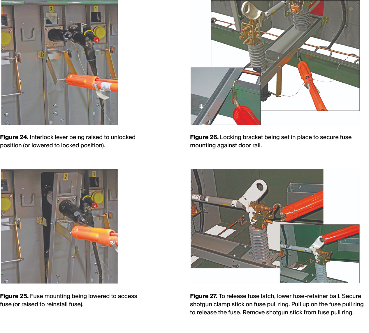
7. The fuse-panel latch interlock prevents access to fuses unless the elbow connector is removed to allow release of the interlock. Secure the shotgun clamp stick to the interlock lever and raise the interlock. See Figures 23 and 24.
8. With the shotgun clamp stick still secured on the interlock lever, pull on the fuse panel; lower it to a horizontal position and release the shotgun clamp stick. See Figure 25.
9. Rotate the locking bracket to secure the fuse access plate down against the lower door stile. The locking bracket is located on the side of the fuse access plate. There is no need to remove the shotgun clamp stick from the interlock unit until the opening process is complete. See Figure 26.
10. Make certain that the fuse retainer bail, located at the pull-ring end of the fuse assembly, has been pivoted off the end fitting. See Figure 27.
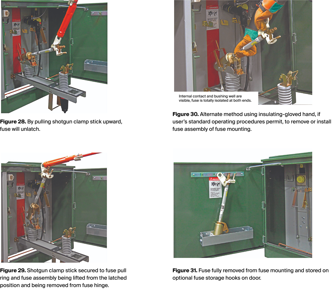
11. Secure the hook of the shotgun clamp stick to the fuse pull ring. Pull and lift the fuse assembly from the fuse mounting. See Figures 25, 28 and 27. Alternately, if user’s standard operating procedures permit, the fuse assembly may be removed from the fuse mounting using an insulating-gloved hand because in the lowered position the fuse mounting is isolated at both ends from high voltage. See Figure 30. If optional fuse storage hooks (suffix -E3 or -E4) are provided, the complete fuse assembly can be stored on the hooks, which are mounted on the fuse-compartment door. See Figure 31.
12. Re-fuse using the procedures included with the fuse manufacturer’s replacement fuse (or refill) unit.
13. Re-install the hook of the shotgun clamp stick onto the pull ring of the fuse assembly. Then lift and place fuse assembly into fuse mounting in the horizontal position, in the reverse of Figures 27, 28, and 29. Alternately, if user’s standard operating procedures permit, the fuse assembly may be placed in the fuse mounting using an insulating-gloved hand because in the lowered position the fuse mounting is isolated at both ends from high voltage. See Figure 31.
14. Before removing hook from fuse pull ring, push firmly to assure that the fuse assembly is completely seated in the hinge, closed and latched.
15. Release the locking bracket that holds the fuse mounting down against the lower door stile. See Figure 26.
16. Secure the shotgun clamp stick to the fuse mounting interlock lever. Then raise the fuse panel and latch it closed.
17. Lower the interlock lever.
18. If applicable, remove the insulating protective cover from the bushing-well insert.
19. Move the elbow connector from the feed-through standoff bushing onto the 200-ampere bushing well insert.
20. If applicable, remove the grounding elbow from the feed-through standoff bushing.
21. Remove the feed-through standoff bushing.
22. Close and padlock the main door before leaving gear.
FUSE RATINGS
(1) 14.4kV Nominal
SM-4 fused units require three S&C Cat. No. 86632R2 SM-4Z fuse holders and three S&C SM-4 fuse refills per fuse compartment. ††
SMU-20 fused units require three S&C Cat. No. 3097 SM-20 fuse end fittings and three S&C SMU-20 fuse units per fuse compartment. ††
DBU fused units require three FP Cat. No. EFA-42 DBU end fittings and three Eaton DBU fuse units per fuse compartment. ††
(2) NX fused units: MIT-PMSW fuse mountings will accommodate one 100 ampere Cooper (McGraw-Edison) type NX current limiting fuse rated 13.5kV, one 80 ampere fuse rated 15kV, or one 40 ampere fuse rated 23kV. ††
(3) 25kV Nominal
SM-4 fused units require three S&C Cat. No. 86633R2 SM-4Z fuse holders and three S&C SM-4 fuse refills per fuse compartment. ††
SMU-20 fused units require three S&C Cat. No. 3097 SM-20 fuse end fittings and three S&C SMU-20 fuse units per fuse compartments. ††
DBU fused units require three FP Cat. No. EFA-42 DBU endfittings and three Eaton DBU fuse units per fuse compartment. ††
(4) NX fused units: MIT-PMSW fuse mountings will accommodate one 100 ampere Cooper (McGraw-Edison) type NX current limiting fuse rated 13.5kV, one 80 ampere fuse rated 15kV, or one 40 ampere fuse rated 23kV. ††
(5) 35kV Nominal
SMU-20 fused units require three S&C Cat. No. 3097 SM-20 fuse end fittings and three S&C SMU-20 fuse units per fuse compartments. ††
DBU fused units require three FP Cat. No. EFA-42 DBU end fittings and three Eaton DBU fuse units per fuse compartment. ††
Applicable to All Voltages:
(6) Ratings expressed in RMS amperes asymmetrical are 1.6 times the symmetrical values listed.
(7) Unit overall ratings are limited to the lowest component rating.
(8) SM-5 fuses cannot be used in MIT-PMSW Pad-mounted Switchgear. Consult Factory.
MAINTENANCE
Maddox Pad-mounted Switchgear does not normally require routine mechanical or electrical maintenance. However, the following are some recommendations for enhancing continued service of the equipment.
1. Yearly mechanical exercising of the switch is recommended.
WARNING: The switchgear must be completely de-energized from all sources before any attempt is made to enter switchgear.
2. Check for cleanliness generally, but particularly for accumulation of any foreign material on insulators.
CAUTION: Do not put grease on switch probe or puffer.
3. If the switch is closed into a short circuit within the making capacity rating and the short circuit is cleared by circuit breakers or fuses, the switch should not sustain damage that will require major repairs. However, the switch should be inspected before returning to service to determine switch condition.
OPTIONAL FEATURES
Standard options may have been supplied that best serve the customer’s needs and operating practices. These are listed below and, if included will be identified by corresponding suffixes to the catalog number.
Base Spacer (option suffixes A2 through A9; AS for stainless steel base spacers) non-compartmented or compartmented.
- Fuse Storage Hooks (option suffix E1 through E5)
- Finish color (option suffix F3)
- Stainless steel enclosure exterior (option suffix F4)
- Hex-head security bolts (option suffix H)
- Key interlocks (option suffixes K1 through K4)
- Cable supports (option suffixes T3 and T4)
- Fault indicators (option suffixes T6 and T7)
- Copper bus (option suffix C)
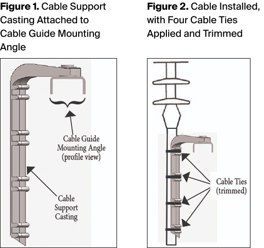
Cable Supports
1. Attach the cable support casting to the cable guide mounting angle, with the arrow on the support casting pointing up. (Figure 1)
2. Train cables as needed for final installation.
3. Remove the protective sheet from the adhesive surface.
Place cable against the adhesive saddle and install (4) cable ties, starting at the top tie position.
5. Trim off the excess end of the cable ties. (Figure 2)


