Guide to Transformer Cooling Classes
The cooling system utilized by a transformer is its cooling class. Cooling protects transformers from heat damage and may also increase the transformer's kVA.
January 12, 2024
How To's
All electrical transformers, even the most efficient, generate heat while in use. Transformers need a cooling system to deal with this heat.
What is a transformer cooling class
The cooling system utilized by a transformer is its cooling class. There are a few different transformer cooling methods. The size and design of a transformer will usually determine which method is best. The cooling system protects against damage from heat. Some cooling systems also increase the transformer's kVA.
In this article, we will cover the most common transformer cooling classes and how these cooling systems are labeled.
Common liquid-filled transformer cooling classes
Below are a few of the most common cooling classes for liquid-filled transformers:
ONAN Transformer
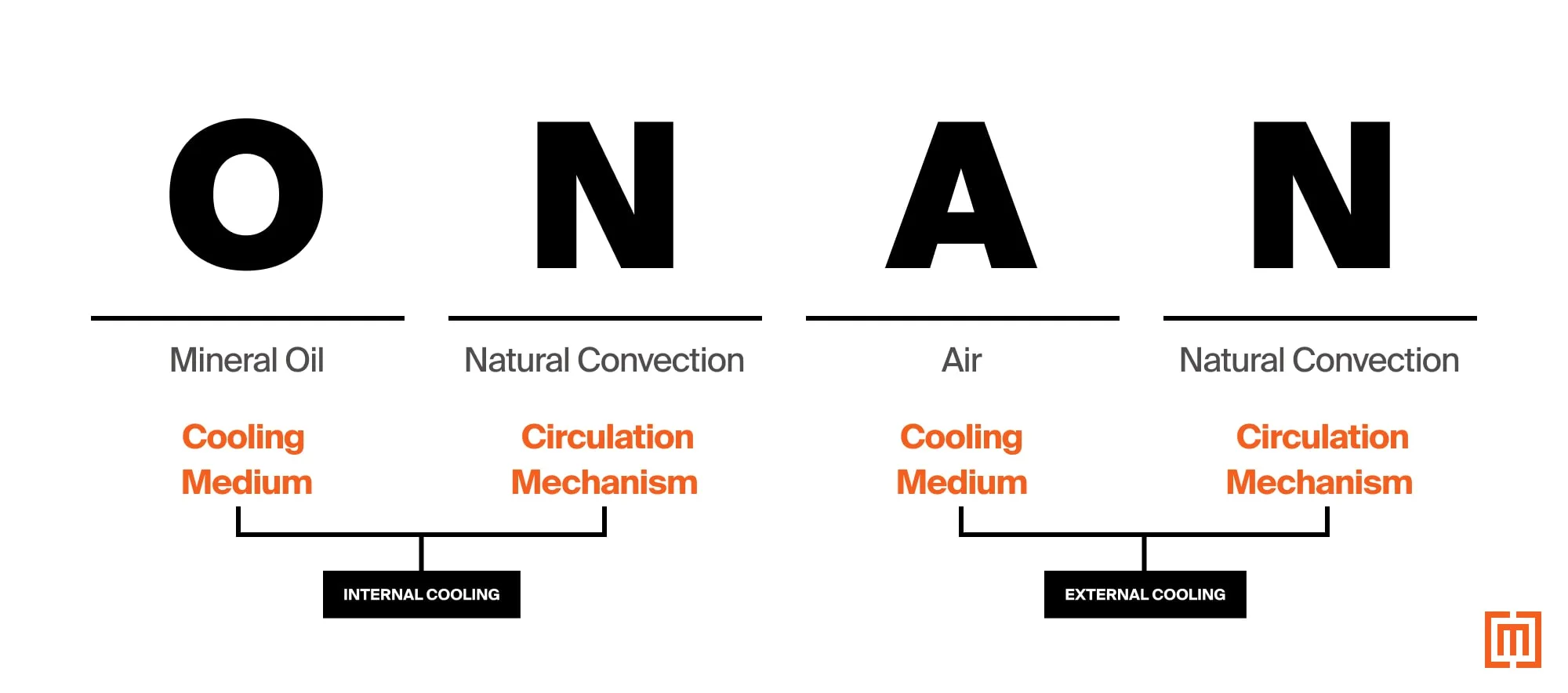
An ONAN transformer is internally cooled by mineral oil (O) with natural convection (N). The external cooling medium is air (A), also via natural convection (N). Transformers of this design manufactured before 2000 are labeled “OA.”
ONAF Transformer
An ONAF transformer is cooled internally by mineral oil (O) and natural convection (N). The external cooling medium is also air (A), but in this case, it’s forced air (F), not natural convection. Transformers of this design manufactured before 2000 are labeled “FA.”
KNAN and KNAF Transformers
KNAN and KNAF transformers use natural esters (K), not mineral oil (O). Just like ONAN and ONAF, the internal cooling mechanism is natural convection (N). The external cooling medium is air (A). The external cooling mechanism is either natural convection (N) or forced air (F).
ONAN/ONAF (KNAN/KNAF) Extended Cooling Class Ratings
Some transformers use extended forced air cooling methods for additional loading capacity. For example, a transformer may be rated ONAN/ONAF (2500/3125 kVA). Up to 2500 kVA, the transformer’s cooling surface (tank and radiators) is air cooled by natural convection. Above 2500 kVA, the transformer’s fans activate. Forcing air across the external cooling surface (radiators). This extended forced air rating increases the total kVA of the transformer by 25%.
Common dry-type transformer cooling classes
AA, AFA, and AA/FA Transformers
These transformers all have ventilation openings in the walls of the enclosure. AA transformers are self-cooled (A) via natural air flow (A).
AFA transformers use ambient air as their cooling medium (A). But they derive their primary cooling method from the forced circulation of air (FA). Normally, the ventilation openings are used for fans to force air (FA) in and out of the unit.
A transformer rated AA/FA is ventilated and self-cooled (AA) with a forced air cooled rating as well (FA). When the self-cooled ratings are exceeded, fans engage to add forced air circulation. Extended forced air rating with fans adds an additional 33% loading capacity above the base, self-cooled rating.
ANV and GA Transformers
A transformer rated ANV is self-cooled (A) and non-ventilated (NV). This means that the transformer does not have any external ventilation. The unit may have fins on the outside of the enclosure to increase surface area for heat transfer.
A GA-rated transformer has a hermetically sealed tank/enclosure. Filled with an internal gas (G) like nitrogen, air, or fluorocarbons. It is also self-cooled (A) by means of natural circulation of air around the outside of the enclosure.
How transformer cooling classes are labeled
Transformer cooling takes place both inside and outside the transformer.
Internal cooling refers to heat dissipation inside the tank around the windings. (How heat is moved away from the core and coils).
External cooling deals with heat dissipation around the outside of the tank and radiators. (Moving heat out of the transformer enclosure).
The transformer cooling class is on the transformer nameplate in an abbreviated letter label.

Liquid filled transformer cooling class abbreviations
Liquid-filled transformers built before 2000 use two or three-letter labels (OA, FA, FOA, FOW). All recent transformers use a four-letter system.
In the four letter system – the first two letters indicate the internal cooling system around the core and coils. The last two letters indicate the external system around the exterior cooling surfaces.
Below is a breakdown of a liquid-filled transformer’s cooling class label:
- Internal cooling medium - first letter
- Internal circulation mechanism - second letter
- External cooling medium - third letter
- External circulation mechanism - fourth letter

Let’s look at each of these cooling mediums and mechanisms in more detail.
Internal Cooling System
1. Internal Cooling Medium (first letter)
The first letter deals with the temperature rating of the internal cooling medium surrounding the windings. "O" represents mineral oil or synthetic fluids with a flashpoint of 300 degrees C and below. Fluid with a flashpoint greater than 300 degrees C, is represented by "K". The letter “L” is used when the fluid has no measurable flashpoint. The most common fluid for less flammable (K) applications is natural ester fluid. There are synthetic options on the market which are used less frequently.
(Learn more about the different types of transformer fluid in this article)
2. Internal Circulation Mechanism (second letter)
Natural Convection
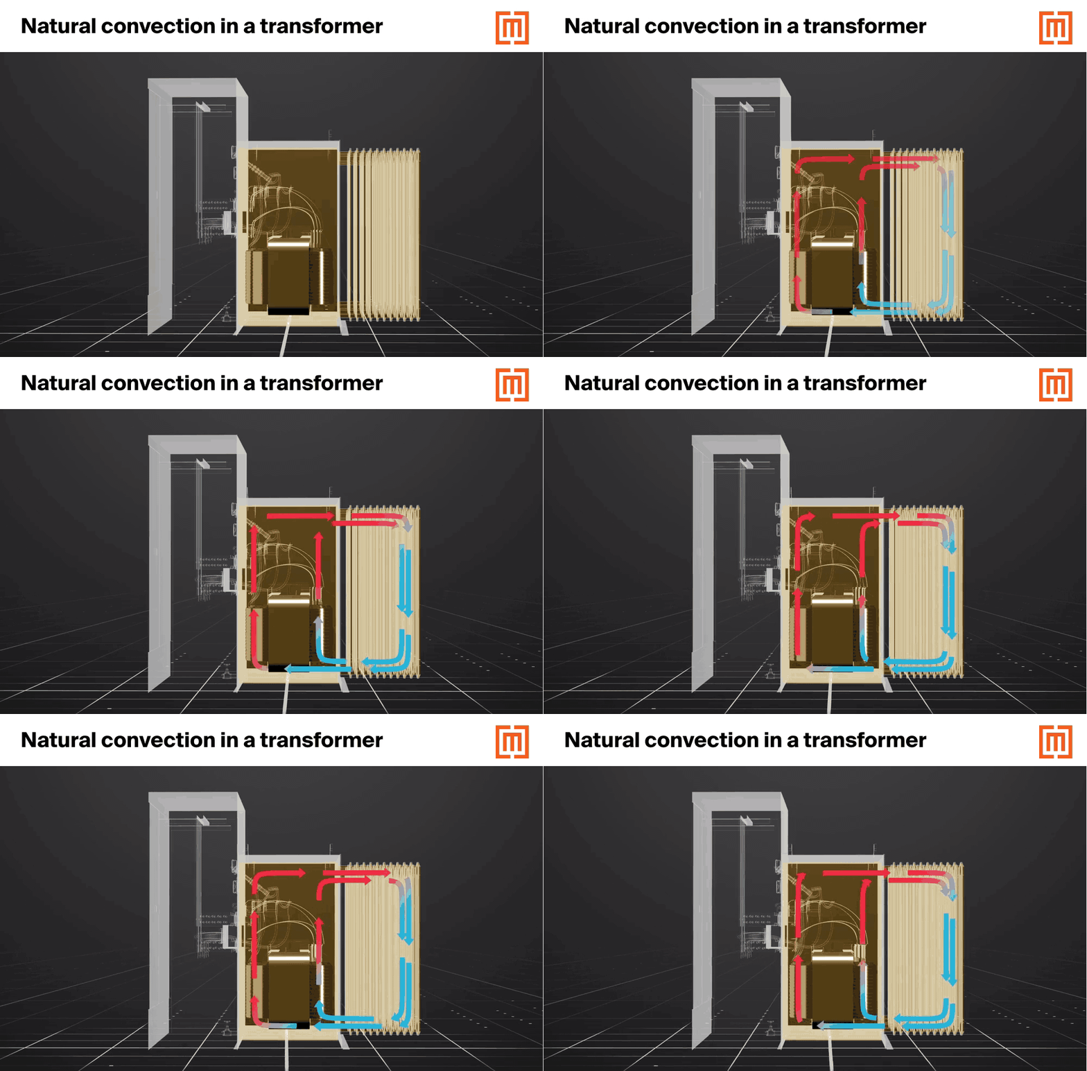
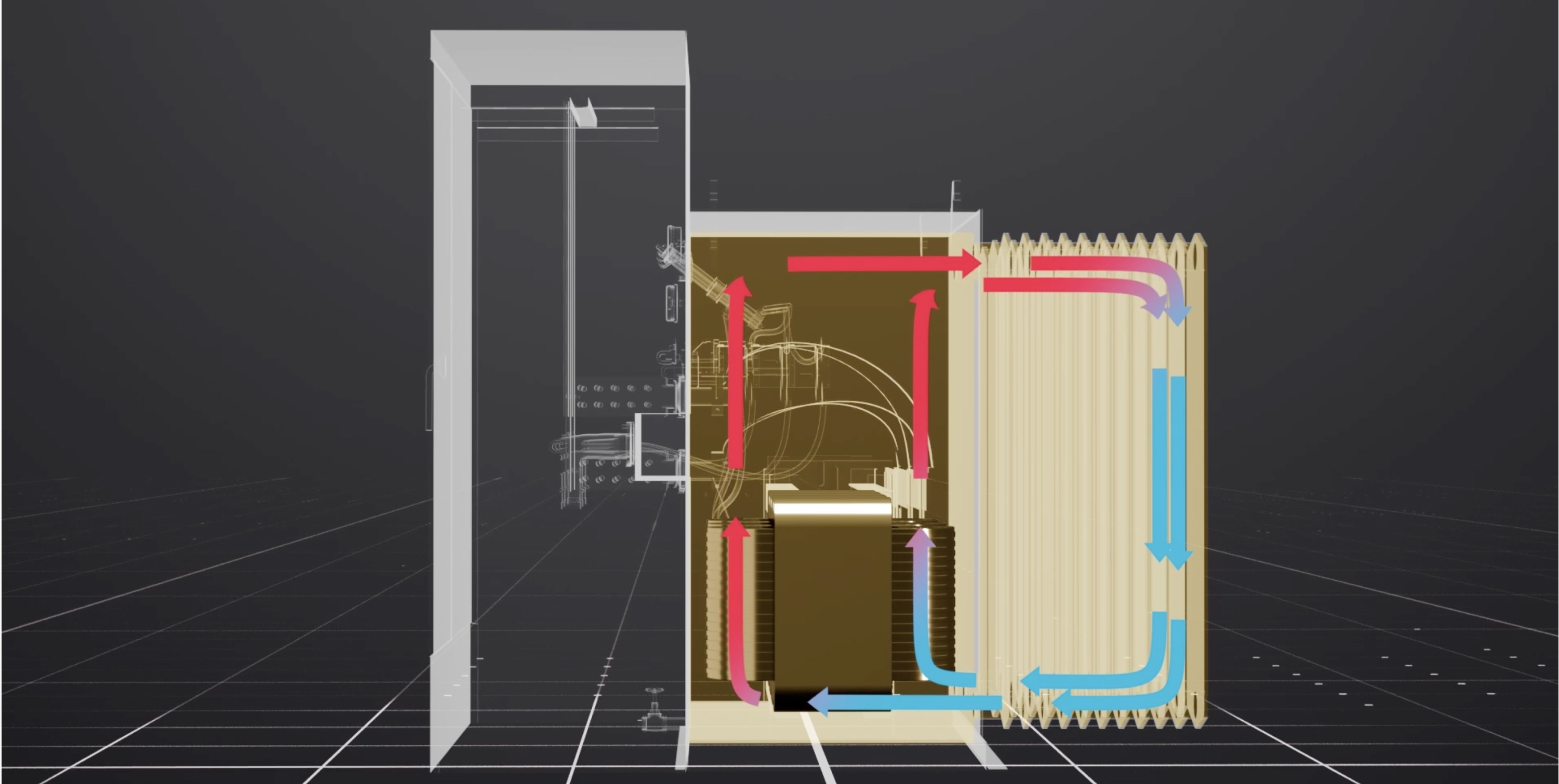
The oil in a transformer tank cools the windings through natural convection (N). The hottest spots in the transformer tank are in and around the transformer windings. As a result, the fluid in and around the transformer core and coils is warmer and more buoyant. This warmer oil flows out toward the less buoyant fluid spaces in the tank. Carrying heat away from the core and coils.
In larger transformers, the warmer fluid flows through radiators. Radiators provide additional surface area for heat to transfer into the ambient air. The fluid in the radiators cools. Then is pushed back towards the windings by the warmer fluid circulating through the tank.

Forced Circulation
Natural convection may not be enough in larger transformers. In such cases, the insulating fluid is pumped in the transformer by heat exchanger equipment and/or radiators. The fluid is moved either freely through the tank (non-directed flow, labeled with the letter “F”) or pumped to flow directly through the windings (directed flow, labeled with the letter “D”).
External Cooling System
3. External Cooling Medium (third letter)
As the hot oil moves away from the windings, it comes in contact with the external cooling surface of the transformer (tank wall and/or radiators). The heat from the oil is then exchanged into an external cooling medium (ambient air). In some cases, this heat exchange is affected by a water cooled surface. Cooling classes such as ONAN and ONAF use an air cooled surface (AN and AF), while ONWF uses a water cooled surface (WF).
4. External Circulation Mechanism (fourth letter)
When air is the external cooling medium, it moves across the cooling surface by natural convection (AN) or forced circulation (AF). Larger substation transformers might use either method for additional cooling and loading capacity (ONAN/ONAF). "ONWF" transformers use water cooling equipment to force water across the transformer surface with heat exchanging equipment.

Dry-type transformer cooling
The cooling classifications for dry-type transformers use similar conventions as oil-filled units. Dry-types all use ambient air for the primary cooling medium. Most units use convection currents generated by the transformer’s heat to create air flow. Vents in the transformer’s enclosure facilitate air flow around the coils. Some units may use fans for forced air circulation inside the transformer enclosure. This adds extra cooling and loading capacity.

Conclusion
If you have any more questions about transformer cooling, or you’re wondering what kind of transformer you need, we’d love to help you get the transformer you need to power on your project.


